Home/
Registry/
Ford/
Ranchero/
1972-1976/
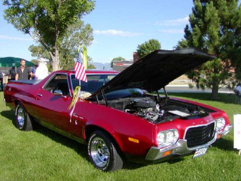
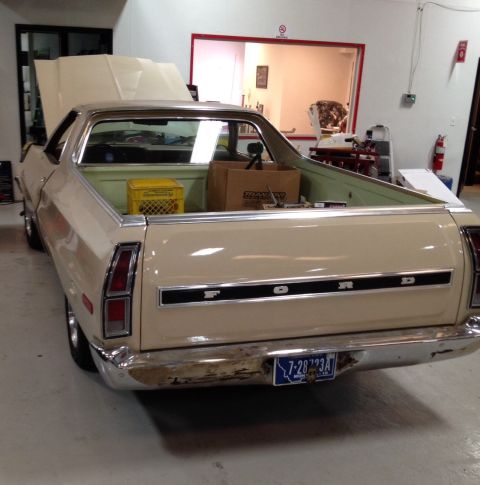
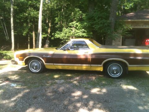
1972 Ford Ranchero/
Photo
supermotors.net/registry/media/843081
Ford V8 Firing Order Diagram - 351W, 351C, 302 HO & Other V8 Cylinder Numbers

Reference · 1972-1976 RancheroAll 31 manual pages
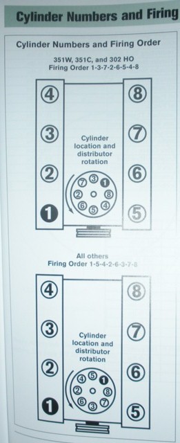
Manual page showing cylinder numbers, firing order, and distributor rotation for 351W/351C/302HO and other V8 engines.
Part of 1972-1976 Ford Ranchero Manual Pages
This manual page, titled "Cylinder Numbers and Firing Order," shows cylinder numbering and firing orders for Ford V8 engines. Two diagrams are presented, each depicting a top view of the engine with the left cylinder bank numbered 4-3-2-1 (front to rear) and the right bank numbered 8-7-6-5 (front to rear). Each diagram also includes a distributor cap illustration labeled "Cylinder location and distributor rotation" showing the plug wire terminal positions and counterclockwise distributor rotation. The upper diagram applies to the 351W, 351C, and 302 HO engines, which use firing order 1-3-7-2-6-5-4-8. The lower diagram applies to "All others" (other Ford V8s covered by this manual), which use firing order 1-5-4-2-6-3-7-8. A reader can learn which firing order applies to their engine, how the cylinders are physically numbered on each bank, and where each spark plug wire connects on the distributor cap relative to distributor rotation. The page was uploaded to a 1972 Ford Ranchero gallery alongside other Cleveland/Windsor engine reference documents.
Is this accurate? Sign in to help verify it.
Frequently asked questions
- What is the firing order for the Ford 351W, 351C, and 302 HO engines?
- According to this document, the 351W, 351C, and 302 HO engines use firing order 1-3-7-2-6-5-4-8.
- What is the firing order for other Ford V8 engines on this page?
- The document states that all other engines use firing order 1-5-4-2-6-3-7-8.
- How are the cylinders numbered on these Ford V8 engines?
- In both diagrams, one bank is numbered 1-2-3-4 (with 1 at the rear in the drawing orientation) and the other bank 5-6-7-8, shown as 4-3-2-1 on the left and 8-7-6-5 on the right when viewed from above.
- Does this document show distributor rotation?
- Yes, each diagram includes a distributor cap illustration labeled 'Cylinder location and distributor rotation' with an arrow indicating rotation direction and the terminal positions for each cylinder.


No comments yet.