Home/
Registry/
Ford/
Ranchero/
1972-1976/
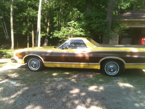
1972 Ford Ranchero/
Photo
supermotors.net/registry/media/798026
Ford 351 Cleveland V8 Oiling System Diagram - Oil Flow Sketch (Mains, Cam, Lifters)

Reference · 1972-1976 RancheroAll 8 schematics
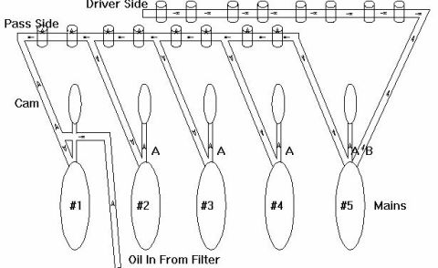
Engine oiling system schematic tracing oil flow from the filter through the main bearings, cam and lifters with directional arrows.
Part of 1972-1976 Ford Ranchero Schematics
This document is a simple line-drawn schematic (sketch) of an engine oiling system, showing oil flow paths through the engine block. Oil enters at the bottom right of the diagram at the point labeled 'Oil In From Filter' and is routed to five main bearing journals, labeled #1 through #5 and collectively marked 'Mains'. From the mains, passages (several marked with the letter 'A', and the #5 main marked 'A B') feed upward. Two horizontal galleries run along the top of the drawing, labeled 'Driver Side' and 'Pass Side' (passenger side), each shown with a row of cylindrical features (representing lifter bores) fed with directional flow arrows. A separate passage on the left is labeled 'Cam', indicating the camshaft oil feed branching near the #1 main. Arrows throughout the sketch indicate the direction of oil flow from the filter inlet, through the main bearing feeds, up to the lifter galleries on both banks. Based on the album context (uploaded among 351 Cleveland reference documents such as head gasket modifications and 'clevorholes'), a reader can use this diagram to understand the oil routing/priority in this engine, mains and cam fed from vertical passages, with the lifter galleries supplied along both banks.
Is this accurate? Sign in to help verify it.
Frequently asked questions
- Where does oil enter the engine in this diagram?
- Oil enters at the point labeled 'Oil In From Filter', located near the #1 main at the bottom left area of the diagram.
- How many main bearings are shown in the oiling diagram?
- Five mains are shown, labeled #1 through #5 and collectively marked 'Mains'.
- What are the two galleries at the top of the diagram?
- They are labeled 'Driver Side' and 'Pass Side', representing the lifter oil galleries on each bank, each shown with a row of lifter bores and flow arrows.
- Which main bearing has two feed passages labeled?
- The #5 main is labeled 'A B', indicating two passages, while mains #2, #3, and #4 are each labeled 'A'.
- Where does the camshaft oil feed branch off?
- The passage labeled 'Cam' branches off near the #1 main on the left (passenger) side of the diagram.

No comments yet.