Ford EEC Self-Test Connector Hookup Diagram - Read Codes with Test Light

Reference · 1983-1992 RangerAll 1 service procedures
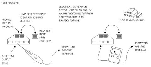
Diagnostic self-test hookup diagram showing how to jump the self-test input and read codes with a test light or analog voltmeter.
Part of 1983-1992 Ford Ranger Service Procedures
This document is a line-art diagram titled "TEST HOOKUPS" showing how to connect test equipment to a vehicle's self-test connectors to read diagnostic trouble codes. It identifies the self-test connectors (a larger multi-pin connector and a smaller single-terminal connector) and labels the key terminals: Signal Return (SIG RTN), Self Test Input (STI, also called the trigger), and Self Test Output (STO). The instructions state that codes can be read on a test light or an analog voltmeter connected from the Self Test Output to battery positive. To start the self-test, the reader is told to jump the Self Test Input to Signal Return. Two hookup arrangements are illustrated: on the left, a test light connected from the STO terminal to the battery positive terminal with a jumper between STI and SIG RTN; on the right, the same jumper arrangement with an analog voltmeter connected from the connector to the battery positive terminal. A reader learns which connector pins to use, how to trigger the self-test, and two acceptable methods (test light or analog voltmeter) for reading the flashed codes. The document itself contains no year, model, or part number information.
Is this accurate? Sign in to help verify it.
Frequently asked questions
- How do I start the self test?
- Jump the Self Test Input (STI, the trigger connector) to Signal Return (SIG RTN) to start the self test.
- How can the diagnostic codes be read?
- Codes can be read on a test light or an analog voltmeter connected from Self Test Output (STO) to battery positive.
- What terminals are identified on the self-test connectors?
- Signal Return (SIG RTN), Self Test Input (STI, also labeled trigger), and Self Test Output (STO).
- Where does the test light or voltmeter connect?
- One lead connects to the Self Test Output on the connector and the other lead goes to the battery positive terminal.






No comments yet.