Ford 2-Barrel Carburetor Exploded Parts Diagram - Motorcraft 2150 Components
Reference · 1983-1992 RangerAll 1 exploded parts diagrams
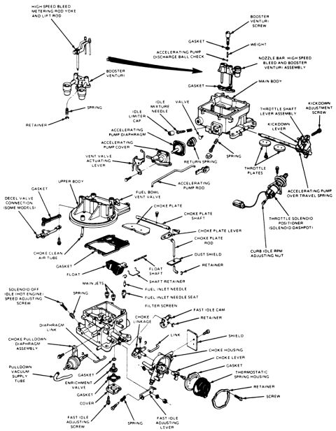
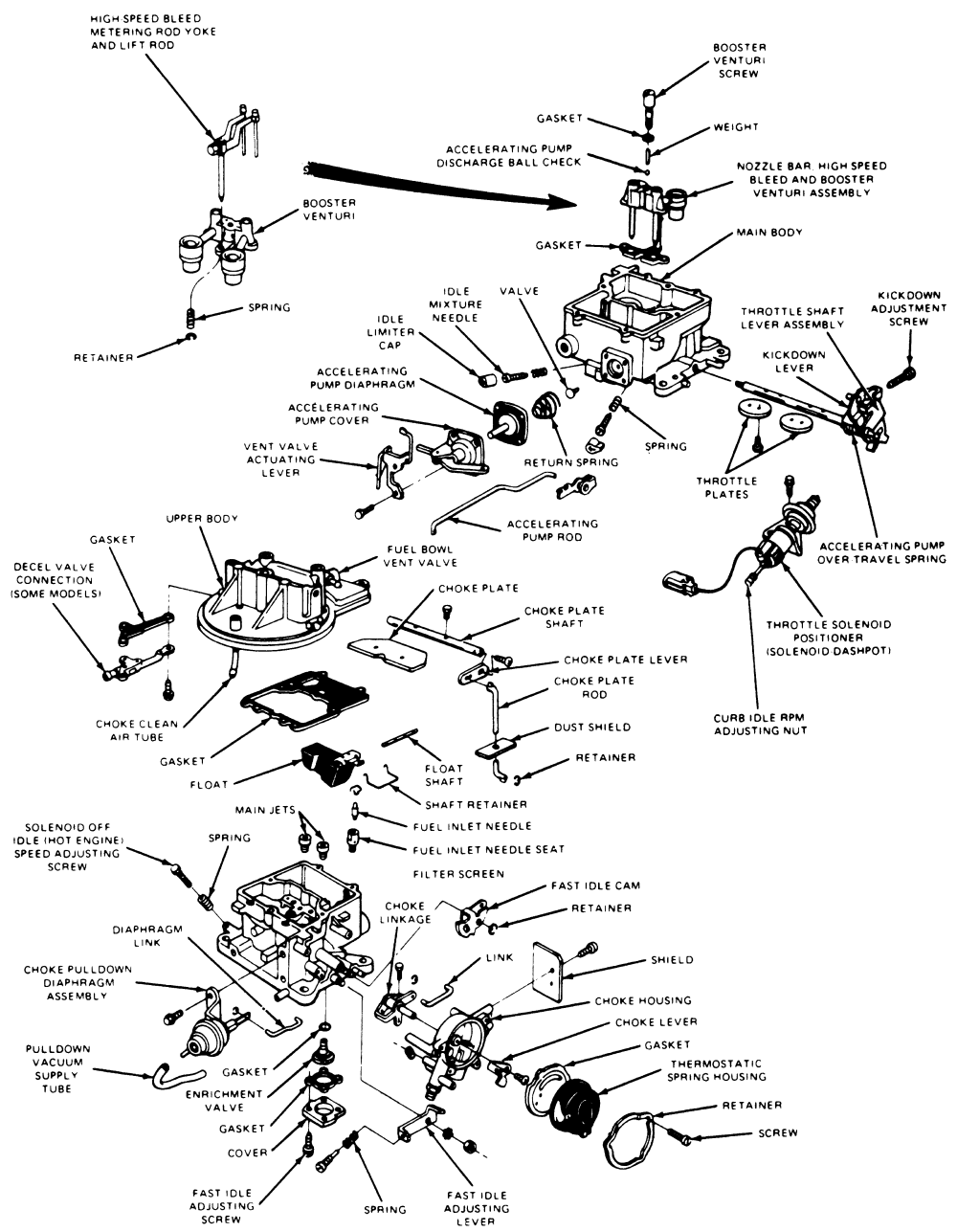
Exploded view of a Ford carburetor naming every component: main/upper body, booster venturi, accelerating pump diaphragm and rod, choke plate/lever/housing, throttle solenoid positioner, float, jets, fast-idle cam, and adjusting screws.
Part of 1983-1992 Ford Ranger Exploded Parts Diagrams
This document is an exploded-view parts diagram of a two-barrel carburetor, showing every major component and its relative assembly position. The illustration is fully labeled with callouts identifying the main body, upper body, booster venturi and nozzle bar assembly, high speed bleed metering rod yoke and lift rod, accelerating pump components (diaphragm, cover, rod, discharge ball check, over-travel spring), idle mixture needle with idle limiter cap, throttle shaft lever assembly, kickdown lever and kickdown adjustment screw, throttle plates, and fuel bowl vent valve. Fuel delivery parts include the float, float shaft, main jets, fuel inlet needle, needle seat, and filter screen. The choke system is detailed with the choke plate, shaft, lever, rod, choke clean air tube, choke pulldown diaphragm assembly, pulldown vacuum supply tube, choke housing, choke lever, thermostatic spring housing, fast idle cam, fast idle adjusting screw and lever. Additional callouts show the throttle solenoid positioner (solenoid dashpot), curb idle RPM adjusting nut, solenoid-off idle (hot engine) speed adjusting screw, enrichment valve, decel valve connection (some models), and various gaskets, springs, retainers, screws, dust shield, and shield. A reader can use this diagram to identify carburetor parts and understand their assembly order for rebuild or repair work. No year, make, model, or part numbers appear on the document.
Is this accurate? Sign in to help verify it.
Frequently asked questions
- What parts make up the accelerating pump system in this carburetor?
- The diagram shows the accelerating pump diaphragm, accelerating pump cover, accelerating pump rod, accelerating pump discharge ball check, and an accelerating pump over travel spring.
- Where is the fuel inlet needle located in the assembly?
- The fuel inlet needle sits with the fuel inlet needle seat and filter screen, near the float, float shaft, shaft retainer, and main jets in the main body area.
- What choke components are shown in the exploded view?
- The choke plate, choke plate shaft, choke plate lever, choke plate rod, choke clean air tube, choke linkage, choke pulldown diaphragm assembly, pulldown vacuum supply tube, choke housing, choke lever, thermostatic spring housing, fast idle cam, and fast idle adjusting screw and lever.
- What idle adjustment points are labeled on this carburetor?
- The diagram labels the curb idle RPM adjusting nut, the solenoid off idle (hot engine) speed adjusting screw, the fast idle adjusting screw, the fast idle adjusting lever, and the idle mixture needle with idle limiter cap.
- Does this diagram show a dashpot or solenoid?
- Yes, it labels a throttle solenoid positioner (solenoid dashpot) and also a decel valve connection noted as fitting some models.
No comments yet.