Home/
Registry/
Ford/
Probe/
1989-1992/
1989 Ford Probe/
Photo
supermotors.net/registry/media/532613
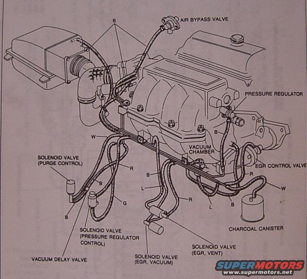
1989 Ford Probe Vacuum Hose Routing Diagram - EGR, Solenoid Valves, Canister
Reference · 1989-1992 ProbeAll 2 vacuum routing diagrams
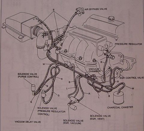
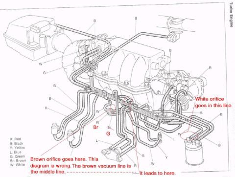
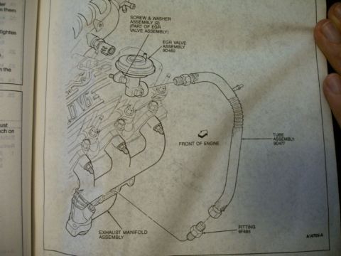
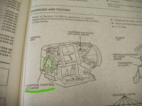
Vacuum hose routing diagram showing air bypass, EGR, and solenoid valves with color-coded vacuum lines.
Part of 1989-1992 Ford Probe Vacuum Routing Diagrams
This document is a scanned vacuum hose routing diagram for an engine, showing an isometric line drawing of the engine assembly (including the air cleaner/intake duct, intake manifold, and valve cover) with vacuum hoses routed between emissions and fuel-system components. Labeled components include the air bypass valve, fuel pressure regulator, vacuum chamber, EGR control valve, charcoal canister, vacuum delay valve, and four solenoid valves: purge control, pressure regulator control, EGR vacuum, and EGR vent. Individual vacuum hoses are marked with single-letter color codes, B, W, R, L, and G, indicating hose color (black, white, red, blue/L, green by common convention, though the diagram itself does not include a color legend). A reader can use this diagram to identify the correct routing of each vacuum line between the intake manifold, solenoid valves, EGR system, charcoal canister, and pressure regulator, which is useful for diagnosing vacuum leaks, emissions faults, EGR problems, or fuel pressure issues, or for reassembly after engine work. The document contains no visible year, make, model, engine designation, or part numbers; it was uploaded as applying to a 1989 Ford Probe. The style is consistent with a factory service manual illustration.
Is this accurate? Sign in to help verify it.
Frequently asked questions
- What components are shown on this vacuum routing diagram?
- The diagram labels the air bypass valve, pressure regulator, vacuum chamber, EGR control valve, charcoal canister, vacuum delay valve, and solenoid valves for purge control, pressure regulator control, EGR vacuum, and EGR vent.
- How many solenoid valves are identified in this diagram?
- Four: solenoid valve (purge control), solenoid valve (pressure regulator control), solenoid valve (EGR, vacuum), and solenoid valve (EGR, vent).
- What do the letters like B, W, R, L, and G on the hoses mean?
- They are markings on the individual vacuum hoses in the diagram identifying specific hoses (color codes). The diagram itself does not include a legend defining them.
- Where does the EGR control valve appear in the layout?
- The EGR control valve is shown on the right rear side of the engine, near the pressure regulator and above the charcoal canister, connected by hoses marked R and W.

No comments yet.