Home/
Registry/
Ford/
Probe/
1989-1992/
1992 Ford Probe/
Photo
supermotors.net/registry/media/265317
Ford Probe Electronic A/C ATC Wiring Diagram - Blower & Actuator Schematic
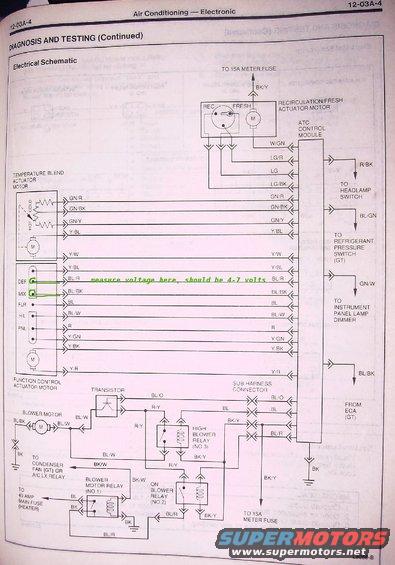
Air conditioning electronic diagnosis schematic showing ATC control module, temperature blend and recirc/fresh actuator motors, blower motor relays, and 15A meter fuse with wire color codes.
Part of 1989-1992 Ford Probe Wiring Diagrams
This is a scanned page (12-03A-4) from a factory service manual section titled 'Air Conditioning: Electronic,' under 'Diagnosis and Testing (Continued).' It presents the complete electrical schematic for the electronic automatic temperature control (ATC) climate system. The diagram shows the ATC control module and its wiring to the recirculation/fresh actuator motor (REC/FRESH positions), the temperature blend actuator motor (HOT/COLD feedback potentiometer), and the function control actuator motor (with DEF, MIX, FLR, H/L, and PNL mode positions). Wire color codes are labeled for every circuit (e.g., W/GN, LG/R, GN/R, Y/BL, BL/R, BL/BK, BK/Y). External circuit connections include the 15A meter fuse, headlamp switch (R/BK), refrigerant pressure switch on GT models (BL/GN), instrument panel lamp dimmer (GN/W), the ECA on GT models, a 40-amp main heater fuse, and the condenser fan (GT) or A/C LX relay. The blower circuit shows the blower motor, a power transistor, and three relays: blower motor relay (No.1), on blower relay (No.2), and high blower relay (No.3), all routed through a sub-harness connector. A hand-added annotation marks the DEF (BL/R) and MIX (BL/BK) wires with 'measure voltage here, should be 4-7 volts,' a defrost/mode-door troubleshooting tip. Diagram reference number: L8058-B.
Is this accurate? Sign in to help verify it.
Frequently asked questions
- What voltage should be measured on the DEF and MIX wires of the function control actuator motor?
- Per the annotation on the schematic, voltage measured at the DEF (BL/R) and MIX (BL/BK) wires should be 4-7 volts.
- What relays are in the blower motor circuit on this electronic A/C system?
- Three relays: Blower Motor Relay (No.1), On Blower Relay (No.2), and High Blower Relay (No.3), plus a power transistor controlling the blower motor.
- What fuses feed the electronic climate control system in this diagram?
- A 15A meter fuse (via BK/Y wires, shown at two points) and a 40 amp main fuse for the heater circuit.
- What wire colors connect the recirculation/fresh actuator motor to the ATC control module?
- W/GN, LG/R, LG, and LG/BK.
- What mode positions does the function control actuator motor have?
- DEF (defrost), MIX, FLR (floor), H/L (heat/level), and PNL (panel), driven by a motor with feedback wires to the ATC control module.
Comments
More from this build


No comments yet.