Home/
Registry/
Pontiac/
Grand Prix/
1997-2003/
1997 Pontiac Grand Prix/
Photo
supermotors.net/registry/media/548133
GM ABS/ETS Service: EBCM/EBTCM & Front Wheel Speed Sensor Removal (5E2-269)
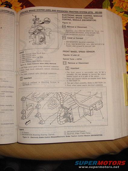
Service procedure for the ABS electronic brake control module and front wheel speed sensor with remove/install steps and figures.
This is page 5E2-269 from a GM factory service manual section covering the Antilock Brake System (ABS) and Enhanced Traction System (ETS). The page contains three service procedures. First, it concludes the Brake Solenoid Valve (ABS) removal procedure with Figure 13, an exploded diagram whose legend identifies the brake solenoid valve Torx bolt, solenoid valve, lip seal, brake modulator, and harness connector; it notes disconnecting the ABS brake motor pack 6-way connector, brake fluid level indicator sensor connector, and two solenoid valve connectors, with an Important note to bleed the system per Section 5. Second, it details removal and installation of the Electronic Brake Control Module/Electronic Brake Traction Control Module (EBCM/EBTCM): the module is released from its bracket via pressure tabs and its electrical connectors disconnected, then reinstalled in reverse. Figure 14 illustrates the module mounting near the I/P harness, mounting housing, and Electronic Brake Control Relay. Third, the page begins the Front Wheel Speed Sensor removal procedure (Figures 15 and 16), requiring special tool J 38764, warning that the front sensor is serviceable only as an assembly (the harness pigtail cannot be serviced separately), and directing the technician to raise the vehicle, remove the tire and wheel, and disconnect the sensor connector.
Is this accurate? Sign in to help verify it.
Frequently asked questions
- How do you remove the EBCM/EBTCM module?
- Release the EBCM/EBTCM from the EBCM/EBTCM bracket using the pressure tabs, then disconnect the EBCM/EBTCM electrical connectors. Installation is the reverse: connect the connectors and slide the module into the bracket until secured by the pressure tabs.
- What special tool is needed for front wheel speed sensor removal?
- Special Tool J 38764 is listed for the front wheel speed sensor procedure (Figures 15 and 16).
- Can the front wheel speed sensor harness pigtail be replaced separately?
- No. The document states the front sensor is serviceable only as an assembly; do not attempt to service the sensor harness pigtail as it is part of the sensor.
- What parts are shown in the Brake Solenoid Valve (ABS) removal diagram (Figure 13)?
- The legend lists: (1) Brake Solenoid Valve Torx bolt, (2) Brake Solenoid Valve, (3) Brake Solenoid Valve Lip Seal, (4) Brake Modulator, and (5) Brake Solenoid Valve Harness Connector.
- What must be done after servicing the brake solenoid valve?
- The Important note says to bleed the brakes as outlined in Bleeding System in Section 5.
Comments
More from this build



No comments yet.