Home/
Registry/
Pontiac/
Grand Prix/
1997-2003/
1997 Pontiac Grand Prix/
Photo
supermotors.net/registry/media/757260
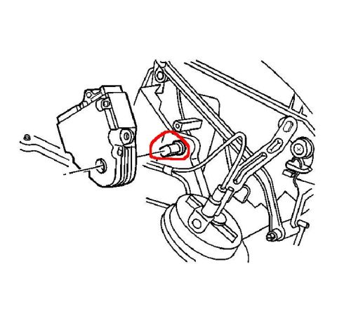
1997 Pontiac Grand Prix HVAC Temperature Actuator Location & Setting Diagram

Service manual illustration using green and red callout arrows to indicate a component or fastener location on an underbody assembly.
This document is a single black-and-white exploded/positional line drawing, apparently taken from a service manual, showing the mounting location and orientation of a temperature (blend door) actuator on an HVAC module. The actuator is drawn at the left, with its gear/linkage side facing outward, and is shown in relation to surrounding components: a stud or bolt being installed into the actuator, connecting linkage rods, a routed harness or vacuum line, a circular drum-shaped component below, and a support bracket with a screw at the right. A leader line and added green and red highlight marks (drawn by the uploader) call attention to a specific alignment feature or slot on the face of the actuator, presumably the point relevant to setting or indexing the actuator, consistent with the upload filename 'Temperature Actuator settings.' The drawing contains no printed text, callout numbers, part numbers, or captions, so no fuse data, torque specifications, or wire colors can be transcribed. A reader can learn the physical location and mounting arrangement of the actuator and which feature on it the uploader considered important for adjustment, but no written specifications are provided by the document itself.
Is this accurate? Sign in to help verify it.
Frequently asked questions
- What does this diagram show?
- It is a line drawing showing an HVAC temperature actuator mounted on the module, with surrounding linkage, a harness/line, a bracket, and a fastener being installed; colored marks highlight a specific feature on the actuator face.
- Does the diagram include torque specs or part numbers?
- No. The illustration contains no printed text, part numbers, torque values, or legends.
- What do the green and red marks indicate?
- They are hand-added annotations pointing to a small oval feature on the actuator face, evidently the alignment/setting point the uploader wanted to highlight, per the filename 'Temperature Actuator settings.'
- Can I identify fuse or wiring information from this document?
- No. This is a mechanical location/mounting illustration only; no wiring colors, connector pins, or fuse data are shown.
Comments
More from this build






No comments yet.