Home/
Registry/
Pontiac/
Grand Prix/
1997-2003/
1997 Pontiac Grand Prix/
Photo
supermotors.net/registry/media/756897
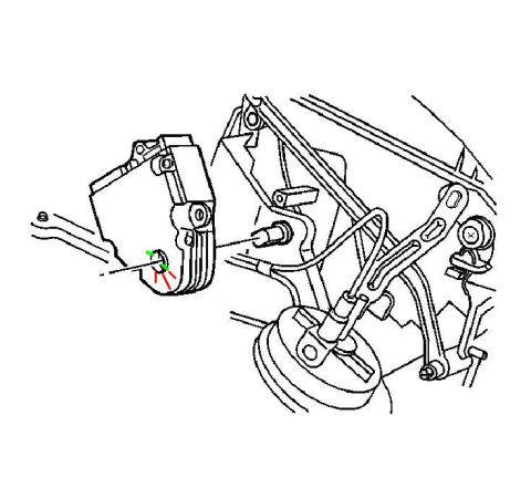
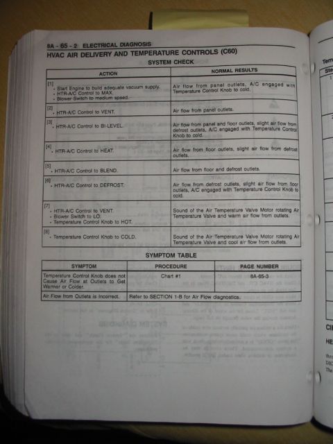
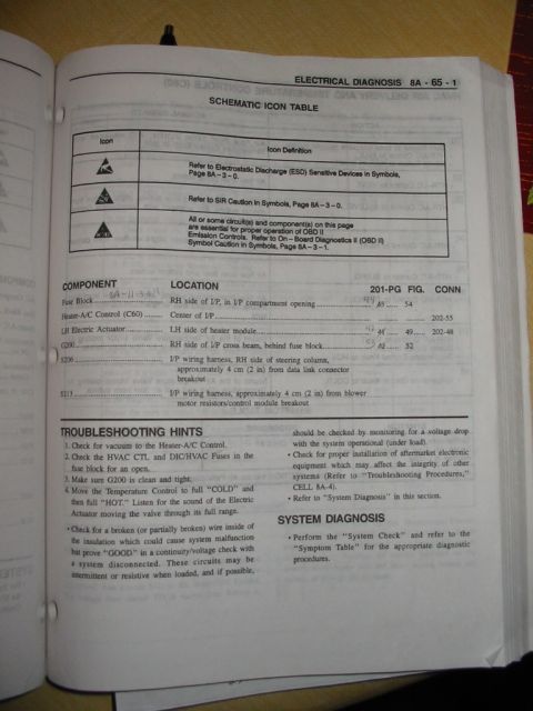
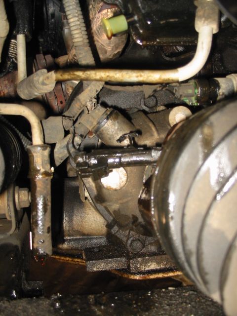
1997 Pontiac Grand Prix HVAC Temperature Actuator Part Location Diagram

Service manual illustration with a red callout circle marking a fastener or sensor location on an underbody steering and suspension assembly.
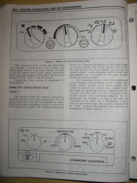
This document is a black-and-white line drawing (apparently from a factory service manual) uploaded to accompany a service procedure for a 1997 Pontiac Grand Prix. It shows an exploded-style component illustration of what the uploader identifies as the temperature actuator area of the HVAC system. Visible in the drawing are an actuator/module housing on the left with mounting screws, a set of linkage arms and rods, a round diaphragm-style actuator at the lower center with an attached lever, and surrounding case structure. A red circle has been hand-added around a small shaft or stud at the center of the illustration, highlighting the specific part the uploader wants to identify — presumably the temperature actuator attachment point or pivot referenced in the companion image 'Temperature Actuator settings.JPG'. The drawing contains no text, callout numbers, part numbers, or dimensions, so a reader can only learn the physical location and appearance of the circled component relative to the actuator housing and linkage, not its part number, torque specs, or adjustment procedure. It would be used together with the accompanying settings page to locate the component during HVAC temperature actuator service or adjustment.
Is this accurate? Sign in to help verify it.
Frequently asked questions
- What does this diagram show?
- It is a line-art illustration of the HVAC temperature actuator area, showing an actuator housing, linkage rods, and a round diaphragm actuator, with a red circle highlighting a specific shaft/stud component at the center.
- Does the diagram list any part numbers or torque specifications?
- No. The illustration contains no text, part numbers, callouts, or torque values — it only shows the location of the circled component.
- What is highlighted in the image?
- A red circle has been drawn around a small shaft or stud between the actuator housing and the linkage, indicating the part the uploader identifies as the temperature actuator part.
Comments
More from this build






No comments yet.