Home/
Registry/
Ford/
Bronco/
1980-1986/
“Still Pending”/
Photo
supermotors.net/registry/media/825051
Ford Bronco Carburetor Choke Cap & Fuel Line Replacement - Manual Page 156
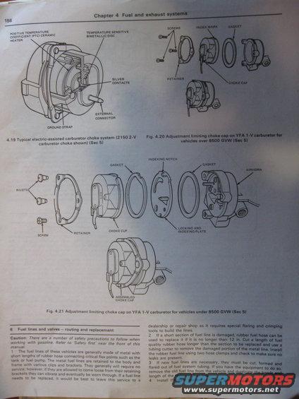
Service manual page showing electric-assisted carburetor choke cap diagrams and fuel-line routing and replacement instructions.
This is page 156 from Chapter 4 ('Fuel and exhaust systems') of a Haynes-style repair manual, uploaded to a 1981 Ford Bronco gallery. The page contains three labeled exploded/cutaway illustrations: Fig 4.19 shows a typical electric-assisted carburetor choke system (2150 2-V carburetor choke), with callouts for the PTC ceramic heater, temperature-sensitive bimetallic disc, silver contacts, external connector, and ground strap. Fig 4.20 shows the adjustment limiting choke cap on the YFA 1-V carburetor for vehicles over 8500 GVW (screws, index mark, gasket, retainer, choke cap). Fig 4.21 shows the adjustment limiting choke cap on the YFA 1-V carburetor for vehicles under 8500 GVW (rivets, screw, retainer, choke cup, gaskets, indexing notch, locking and indexing plate, airhorn, assembled choke cap). Below the figures, Section 6 'Fuel lines and valves – routing and replacement' begins, with a gasoline safety caution and steps 1–4 describing metal fuel line construction, when to use rubber hose (repairs no longer than 12 in with two hose clamps), and how to cut, form and flare replacement fuel system tubing by duplicating the old line's bends and length.
Is this accurate? Sign in to help verify it.
Frequently asked questions
- What components make up the electric-assisted carburetor choke on the 2150 2-V carburetor?
- Per Fig 4.19, it includes a positive temperature coefficient (PTC) ceramic heater, a temperature-sensitive bimetallic disc, silver contacts, an external connector, and a ground strap.
- How is the adjustment limiting choke cap different on YFA 1-V carburetors over vs under 8500 GVW?
- Fig 4.20 (over 8500 GVW) shows the cap retained by screws with an index mark, gasket, retainer and choke cap. Fig 4.21 (under 8500 GVW) uses rivets and a screw with a retainer, choke cup, two gaskets, a locking and indexing plate with an indexing notch, mounted to the airhorn.
- Can I use rubber hose to repair a damaged metal fuel line?
- Yes, if the damaged section is no longer than 12 inches. Cut a length of fuel-quality rubber hose longer than the section, remove the damaged metal portion with a tubing cutter, install the hose with two hose clamps, and check for leaks.
- How should completely new fuel lines be made?
- They must be cut, formed and flared out of fuel system tubing; remove the old line and duplicate its bends and length. The manual notes full line replacement is best left to a dealership or repair shop since it requires special flaring and crimping tools.
Comments
More from this build


No comments yet.