Home/
Registry/
Ford/
Bronco/
1980-1986/
“Still Pending”/
Photo
supermotors.net/registry/media/825052
Ford Bronco Automatic Choke Diagrams - 2150, 7200 VV & 4180-C Carburetors
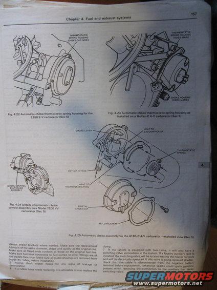
Service-manual figures of automatic-choke thermostatic spring housings and choke assemblies for Motorcraft 2150 2V, Holley-C 4V, 7200 VV and 4180-C 4V carburetors.
This is page 157 from Chapter 4 ("Fuel and exhaust systems") of an automotive repair manual, illustrating automatic choke components on several Ford carburetors. Four figures are shown: Fig. 4.22 depicts the automatic choke thermostatic spring housing on the 2150 2-V carburetor, pointing out the thermostatic spring housing choke cap index; Fig. 4.23 shows the same housing installed on a Holley-C 4-V carburetor, identifying the spring housing index mark and choke housing index marks; Fig. 4.24 details the automatic choke control (diaphragm) assembly on a Model 7200 VV carburetor; and Fig. 4.25 is an exploded view of the automatic choke assembly for the 4180-C 4-V carburetor, labeling the choke lever, heat-to-vacuum pick-up, thermostatic spring, hot air intake, heat-to-thermostatic ring, bimetal choke cap, and holding strap. The accompanying text (steps 5-7 of a fuel line procedure) covers replacing fuel tubing with matching diameter, double-flare fittings, inspecting rubber hoses for leakage or deterioration, replacing clamps with hoses, and dual-tank switching valves. It notes the electrically operated switching valve on factory auxiliary tanks is located near the heater controls, and warns to disconnect the negative battery cable before replacement to avoid sparks igniting gasoline.
Is this accurate? Sign in to help verify it.
Frequently asked questions
- What parts make up the automatic choke assembly on the 4180-C 4-V carburetor?
- The exploded view (Fig. 4.25) shows the choke lever, heat to vacuum pick-up, thermostatic spring, hot air intake, heat to thermostatic ring, bimetal choke cap, and holding strap.
- Which carburetors are covered by the choke illustrations on this page?
- The 2150 2-V, a Holley-C 4-V, the Model 7200 VV, and the 4180-C 4-V carburetors.
- Where is the fuel tank switching valve located if the truck has a factory auxiliary tank?
- The document states the electrically operated switching valve will be located next to the heater controls.
- What safety step is required before replacing the fuel tank switching valve?
- Double-check that the cable is disconnected from the negative battery terminal, otherwise sparks could ignite gasoline present when removing the connection.
- What type of flare should fuel lines connected to fuel pumps have?
- The manual says fuel lines connected to fuel pumps or other fittings must be of the double flare type.
Comments
More from this build








No comments yet.