Home/
Registry/
Ford/
Mustang II/
1974-1978/
1978 Ford Mustang II/
Photo
supermotors.net/registry/media/833449
1978 Ford Mustang II Custom Gauge Cluster Panel Layout Blueprint
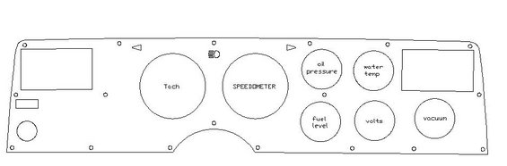
Template drawing of a dash gauge panel with openings labeled Tach, Speedometer, oil pressure, water temp, fuel level, volts and vacuum.
This document is a simple black-and-white line drawing (blueprint-style layout) of a custom or replacement instrument cluster panel, uploaded to a 1978 Ford Mustang II gallery. It shows the planned gauge layout for a dashboard insert: a large tachometer opening and a large speedometer opening on the left/center of the panel, followed by four smaller gauge openings arranged in two rows, oil pressure and water temp on top, fuel level and volts below, plus a separate vacuum gauge opening at the far right. Additional features include two rectangular cutouts at each end of the panel (possibly for vents, warning-light clusters, or switches), left- and right-pointing triangular cutouts for turn-signal indicator arrows, a high-beam/headlamp indicator symbol, a small rectangle and circular cutout at lower left, perimeter screw-hole locations, and a curved bottom-center notch apparently for steering column clearance. The drawing contains no dimensions, measurements, part numbers, wire information, or year/model text; it functions purely as a positional layout showing which gauges go where in the fabricated cluster panel. A reader can learn the intended gauge arrangement (tach, speedometer, oil pressure, water temp, fuel level, volts, vacuum) and indicator positions, but not sizes or fitment specifics.
Is this accurate? Sign in to help verify it.
Frequently asked questions
- What gauges are shown in this instrument cluster layout?
- The layout includes a tachometer, speedometer, oil pressure, water temp, fuel level, volts, and a vacuum gauge.
- How are the small gauges arranged on the panel?
- Oil pressure and water temp are on the top row, fuel level and volts are below them, and the vacuum gauge sits separately at the far right.
- Does the drawing include indicator lights?
- Yes: there are left and right triangular cutouts for turn-signal arrows near the top center and a headlamp/high-beam indicator symbol between the tach and speedometer.
- Are any dimensions or part numbers given in this blueprint?
- No. The drawing shows only the gauge positions, cutouts, and screw-hole locations; no measurements, part numbers, or year/model information appear.
- Why is there a notch in the bottom center of the panel?
- The drawing shows a curved cutout at the bottom center of the panel; no explanation is given in the document, though its position suggests clearance (e.g., for a steering column).
Comments
More from this build
No comments yet.