Automotive repair document provides instructions for testing ignition system components.
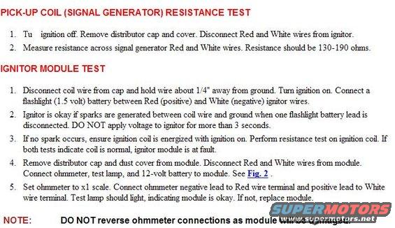
PICK-UP COIL (SIGNAL GENERATOR] RESISTANCE TEST 1 Tu lymmn oer Remme dlsmbutmr cap and (ma Dlsconnect Red and his wesom lgnltor 2 Measure reslstance across Slgnal generatm' Red and his wes Reslstance should be 130190 ohms IGNITUR MODULE TEST 1 Dtsconnect coll we som cap and hold we about 1 4 awzw Emu gound rum lgnmon on Connect a ashhght (1 5 u all) batterv between Red ([905th e) and his (negam e) lgnltor wes Ignltor ls okav lfspaeks are generated between coll we and yound when one ashhgut batterv lead ls dsconnected DO NOT applv oltage to 19mm for more than 3 seconds 3 Knospark occurs ensurelglmoncolllsenergzedwlthlylmnn on Pafm'm reslstance test on lgnmon col If both tests lnducate col ls normal lmtm' module ls at fault 4 Ranme dlsmbutnr cap and dust (ma 'om module Dlsconnect Red and his wesom module Connect ohmmeter test lamp and 124011 bane-(v to module See Fig. 2 5 Set ohmmeter to )1} scale Connect ohmmeter negame lead to Red we temnal and poslme lead to Mute we temnal Test lamp should 11le lndlcanng module ls mkav Knot replace module NOTE: DO NOT reverse ohmmeter connections as module will be damaged.
Comments
More from this build


No comments yet.