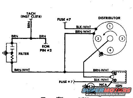
Ignition Coil, Distributor & Tach Signal Wiring Diagram - Fuse #7 Circuit
Reference · 1993-1997 ProbeAll 65 wiring diagrams
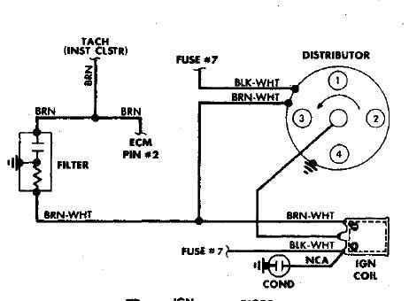
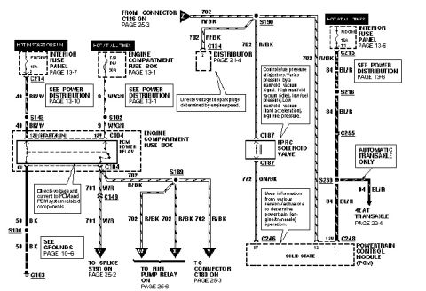
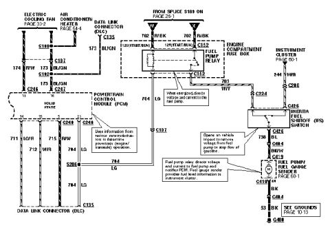
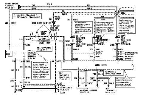









Wiring diagram showing distributor, ignition coil, noise filter, tachometer and ECM ignition connections.
Part of 1993-1997 Ford Probe Wiring Diagrams
This document is a wiring diagram of an ignition/tachometer circuit showing how the tachometer signal is routed from the ignition system to the instrument cluster. A BRN (brown) wire runs from the TACH (instrument cluster) through a noise filter (dashed box containing a resistor and a grounded capacitor) and also feeds ECM PIN #2. A BRN-WHT (brown-white) wire connects the filter circuit to the ignition coil and distributor. Power is supplied through FUSE #7 on BLK-WHT (black-white) and via an NCA wire to the ignition coil, which also has a condenser (COND) to ground. The distributor cap is drawn with four terminals numbered 1 through 4 and an arrow indicating counterclockwise rotor rotation, with the distributor body grounded. From this diagram a reader can learn the wire colors (BRN, BRN-WHT, BLK-WHT, NCA), the fuse feeding the ignition coil (Fuse #7), the tach signal path including the RFI filter, and the ECM pin (Pin #2) that receives the ignition reference/tach signal. No year, make, model, or part numbers are stated on the visible portion; the bottom caption is cut off.
Is this accurate? Sign in to help verify it.
Frequently asked questions
- What fuse powers the ignition coil in this diagram?
- Fuse #7 feeds the ignition coil, via a BLK-WHT wire and also via an NCA wire to another coil terminal.
- What wire colors are used in the tach/ignition circuit shown?
- BRN (brown) from the tach/instrument cluster, BRN-WHT (brown-white) between the filter, distributor, and ignition coil, BLK-WHT (black-white) from Fuse #7, and an NCA wire to the ignition coil.
- Which ECM pin receives the tach/ignition signal?
- ECM Pin #2 connects to the BRN wire in the tach circuit.
- Is there a filter in the tachometer circuit?
- Yes, the BRN tach wire passes through a filter shown as a resistor with a capacitor to ground before joining the BRN-WHT wire to the ignition coil/distributor.
- How many distributor cap terminals are shown and which way does the rotor turn?
- The distributor cap is shown with four numbered terminals (1-4) and an arrow indicating counterclockwise rotation.






No comments yet.