Ford Probe Control Module Bench Test Diagram - Ohmmeter & Test Light Hookup
Reference · 1993-1997 ProbeAll 12 service procedures

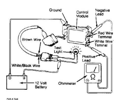









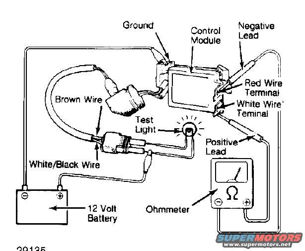
Service test illustration showing a control module wired to a 12-volt battery, test light and ohmmeter with labeled leads.
Part of 1993-1997 Ford Probe Service Procedures
This document is a labeled illustration showing a bench-test setup for a control module. The diagram depicts a control module connected to a 12 volt battery, a test light, and an ohmmeter. Callout labels identify the wiring and connection points: a Ground connection to the module, a Brown Wire and a White/Black Wire running through a connector to the battery, and Red Wire Terminal and White Wire Terminal locations on the control module's connector. The ohmmeter's Negative Lead and Positive Lead are shown probing the module's terminals, and the test light is wired into the circuit and illustrated as illuminated. The figure carries the reference number 29135. No text on the drawing itself states a vehicle year, make, model, or the specific system the control module belongs to, so applicability must be inferred from the album context (uploaded to a 1993 Ford Probe gallery among Probe/Mazda 626 service scans). A reader can learn how to hook up the battery, test light, and ohmmeter leads to the module's terminals by wire color in order to perform this diagnostic test procedure.
Is this accurate? Sign in to help verify it.
Frequently asked questions
- What tools are shown in this control module test setup?
- A 12 volt battery, a test light, and an ohmmeter with positive and negative leads.
- Which wire colors are identified in the diagram?
- A brown wire, a white/black wire, and terminals for a red wire and a white wire on the control module.
- Where do the ohmmeter leads connect?
- The negative lead connects at the red wire terminal area of the control module and the positive lead at the white wire terminal, per the callouts.
- What power source is used for this test?
- A 12 volt battery, connected via the brown wire and white/black wire.






No comments yet.