Ford Probe DIY High-Speed Fan Trigger Circuit - LM393 Comparator Schematic
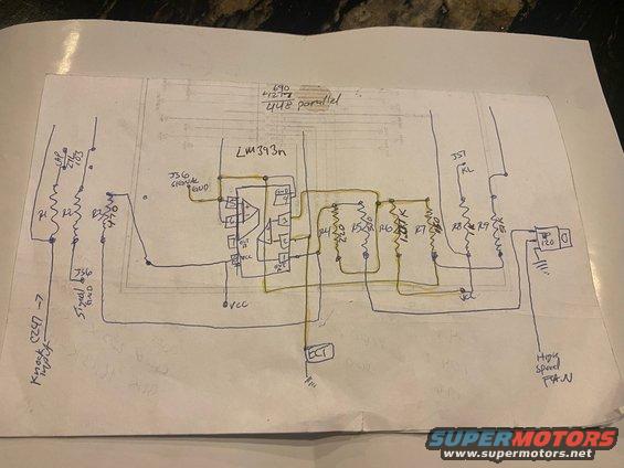
Hand-drawn electronic circuit schematic using an LM393 comparator and resistors to control a high-speed fan.
This is a hand-drawn electronic schematic sketched in pen (with some traces highlighted in yellow) over a faint printed factory wiring diagram, uploaded to a 1993 Ford Probe gallery. The circuit is built around an LM393n dual comparator IC, with both comparator sections and pin numbers (1–8) drawn out. The left side shows a 'Knock C247 -7' input feeding through resistors R1, R2, and R3 (470 ohms noted) and a capacitor marked '27L 103', with 'JS6 Signal GND' reference connections. The output side uses a resistor network (R4 220, R5 330, R6 ~1.27K, R7, R8, R9, 51K) and drives a TIP120 power transistor whose output is labeled 'High Speed FAN'. An 'ECT' (engine coolant temperature) node is tied into the comparator network and grounded. Labels 'J57' and 'KL' appear on the right side, and VCC supply points are marked in two places. A math note at top reads '690 + 127? / 448 parallel', apparently a parallel-resistance calculation. The document appears to be a DIY circuit for triggering a high-speed cooling fan based on knock/ECT signals, likely designed by the owner for a Ford Probe cooling fan modification. No year, model, or part-number applicability is stated on the document itself.
Is this accurate? Sign in to help verify it.
Frequently asked questions
- What IC does this fan trigger circuit use?
- An LM393n dual comparator, with pins 1–8 drawn including OUT A, OUT B, VCC (pin 8) and GND (pin 4).
- What transistor drives the high-speed fan output?
- A TIP120 power transistor; its output is labeled 'High Speed FAN' with a ground connection.
- What resistor values are shown in the schematic?
- Legible values include 470 (R3), 220 (R4), 330 (R5), approximately 1.27K (R6), and a 51K resistor near R9; R1, R2, R7 and R8 values are unclear.
- What inputs feed the circuit?
- A 'Knock C247 -7' input on the left (through R1/R2 and a capacitor marked 27L 103) and an 'ECT' signal node highlighted in yellow that ties into the comparator network.
- What ground references are labeled?
- 'JS6 Signal GND' is labeled twice as the signal ground reference, plus chassis-ground symbols at the ECT node and TIP120 output.
Comments
More from this build








No comments yet.