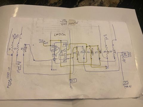
Ford Probe ECT/CLT Sensor Circuit Mod Schematic - Before/After Comparator Sketch
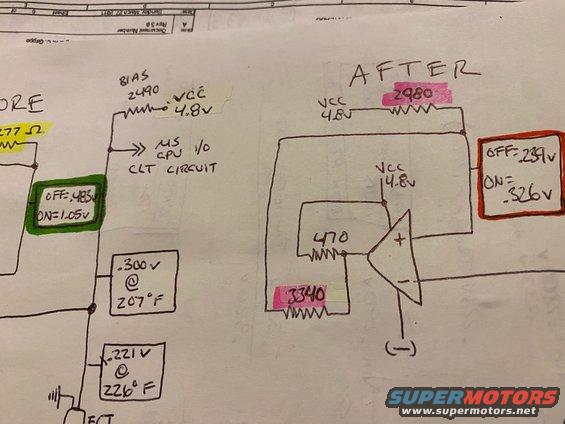
Close-up of a hand-drawn before/after op-amp circuit schematic for a CLT sensor circuit with voltage values.
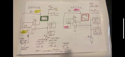
This is a hand-drawn engineering sketch, drawn on the back of (or over) a printed schematic sheet dated Sunday, March 27, 2011 (Rev 3.0, Sheet 6, name partially reading "...Grippo"). It documents a before/after modification of a coolant temperature (CLT/ECT) sensing circuit feeding a CPU I/O input (labeled "MS CPU I/O CLT CIRCUIT", suggesting a MegaSquirt-style ECU). The BEFORE circuit shows a 2490-ohm bias resistor to VCC (4.8v) with an ECT sensor to ground, switching thresholds of OFF=.483v / ON=1.05v, and measured sensor voltages of .300v @ 207°F and .221V @ 226°F. The AFTER circuit adds a comparator/op-amp stage powered by VCC 4.8v, with a 2980-ohm pull-up, a 470-ohm resistor into the + input, and a 3340-ohm resistor to ground, producing new switching thresholds of OFF=.239v / ON=.326v. A reader can learn the resistor values, supply voltage, temperature-to-voltage calibration points, and the changed on/off trip voltages resulting from the circuit modification — likely for a cooling-fan or temperature-switch trigger circuit.
Is this accurate? Sign in to help verify it.
Frequently asked questions
- What supply voltage does the CLT/ECT circuit use?
- VCC is shown as 4.8v in both the before and after circuits.
- What are the ON/OFF voltage thresholds before the modification?
- OFF = .483v and ON = 1.05v.
- What are the ON/OFF thresholds after the modification?
- OFF = .239v and ON = .326v.
- What sensor voltages correspond to specific temperatures?
- .300v at 207°F and .221V at 226°F.
- What resistor values are used in the modified (AFTER) circuit?
- A 2980-ohm resistor to VCC 4.8v, a 470-ohm resistor into the comparator's + input, and a 3340-ohm resistor; the original bias resistor was 2490 ohms.
Comments
More from this build








No comments yet.