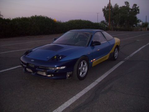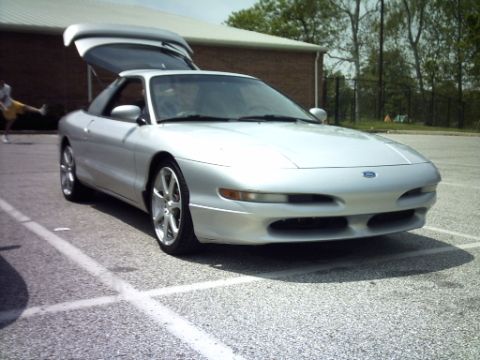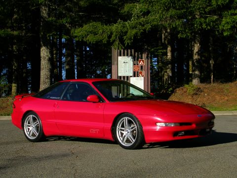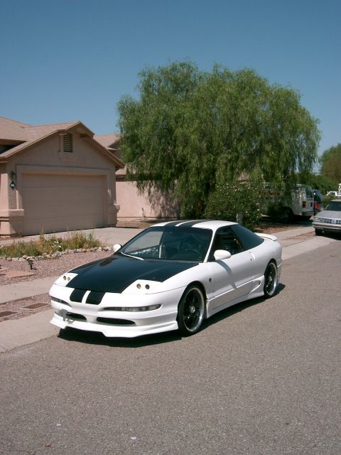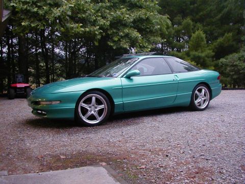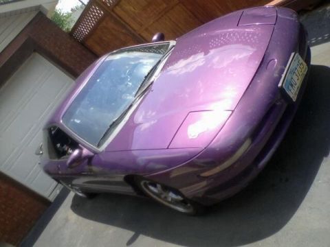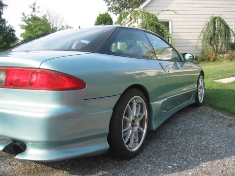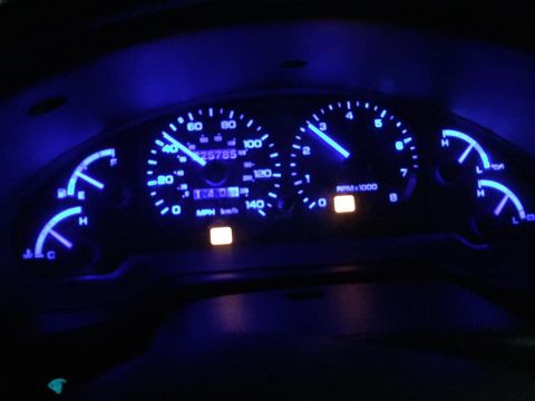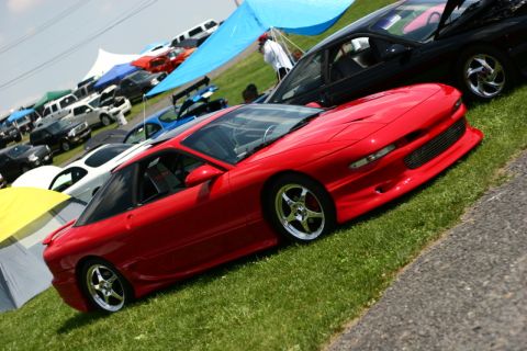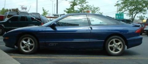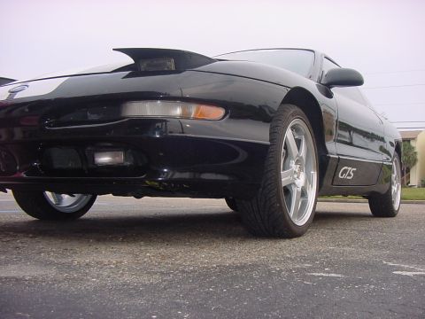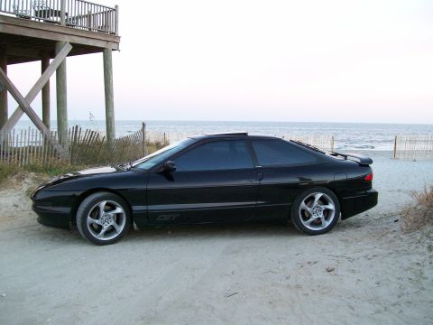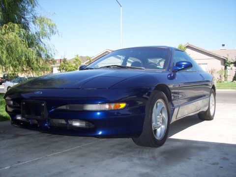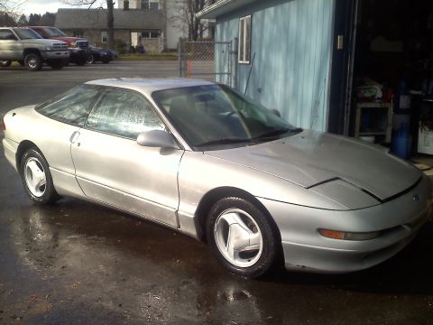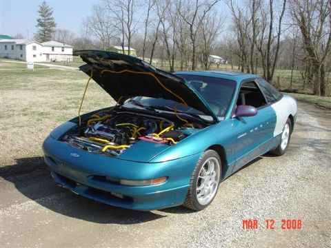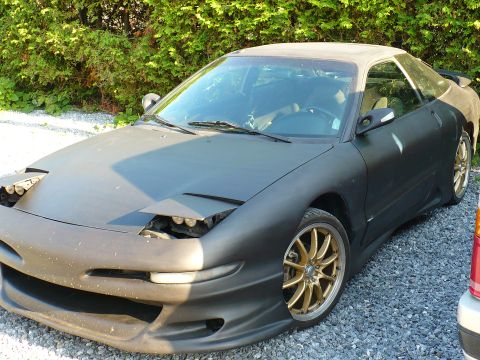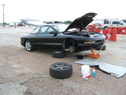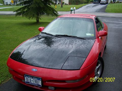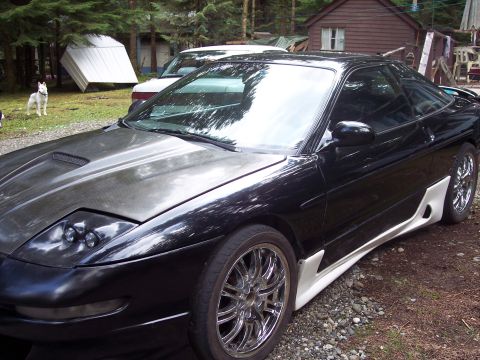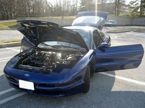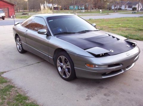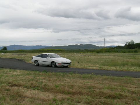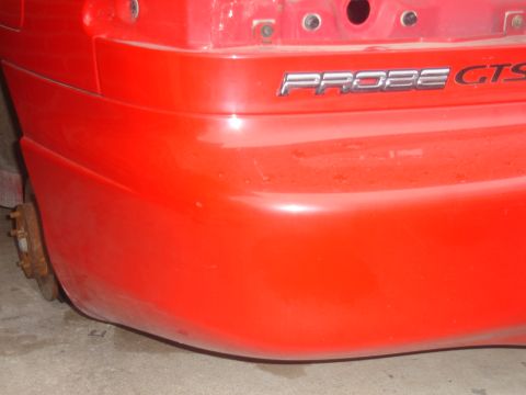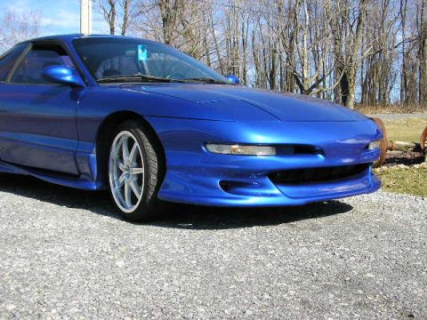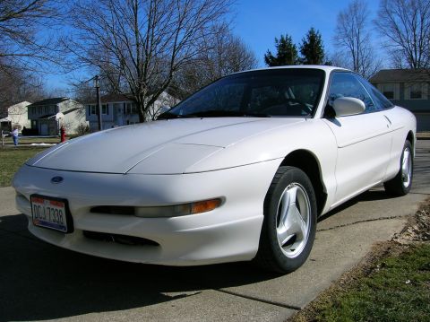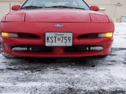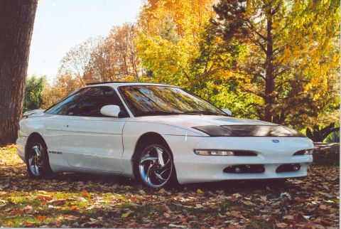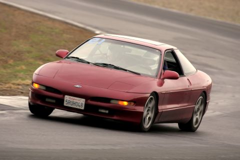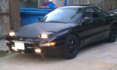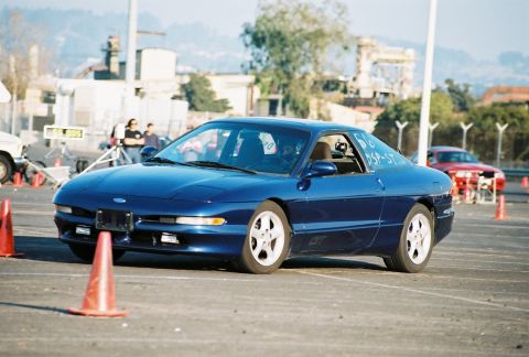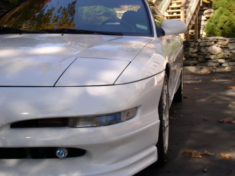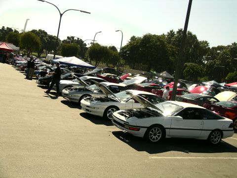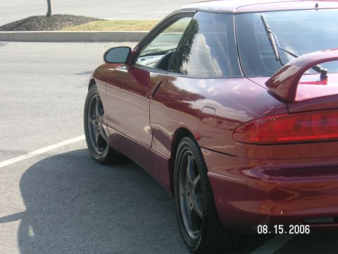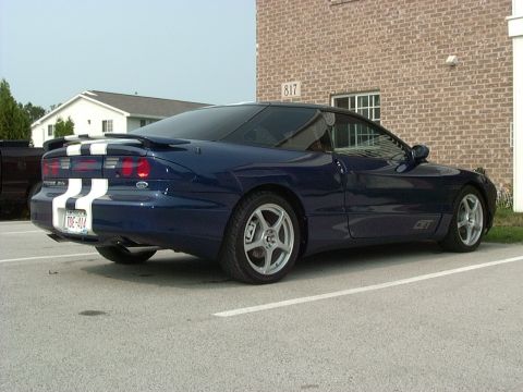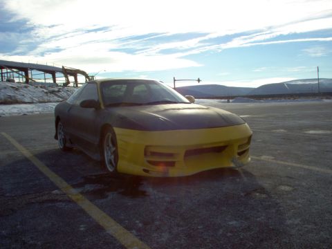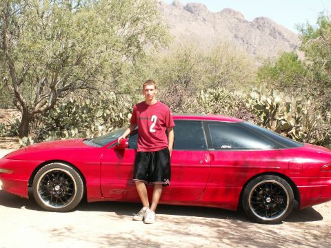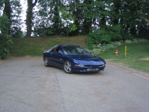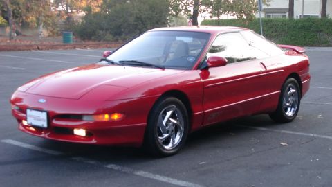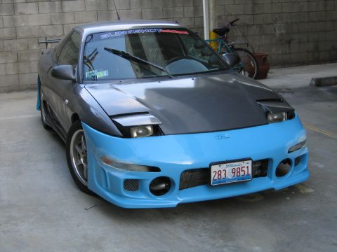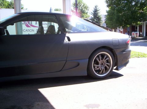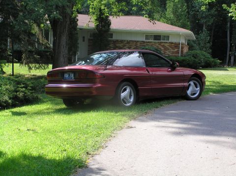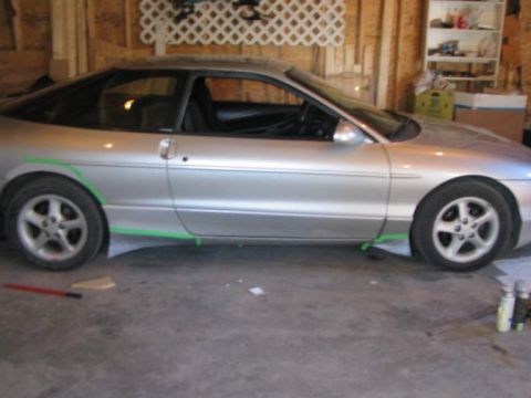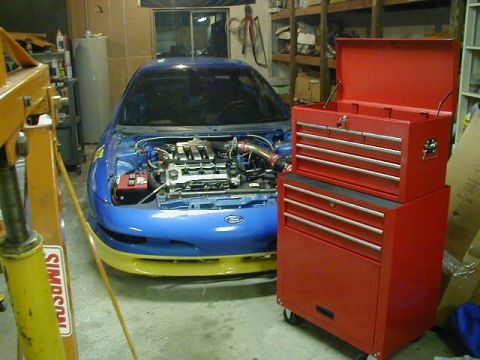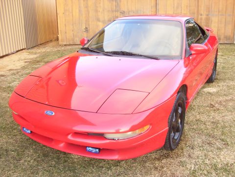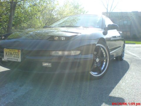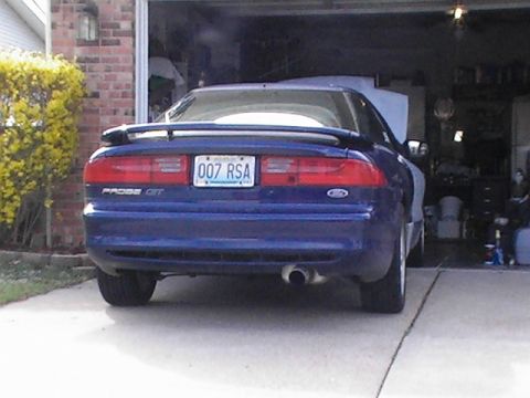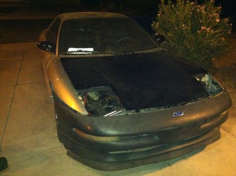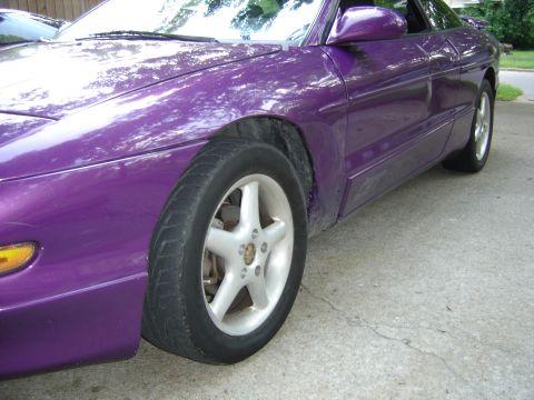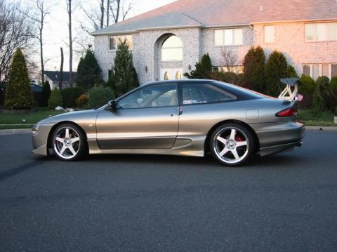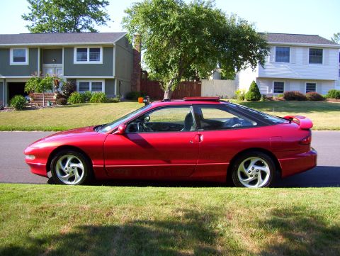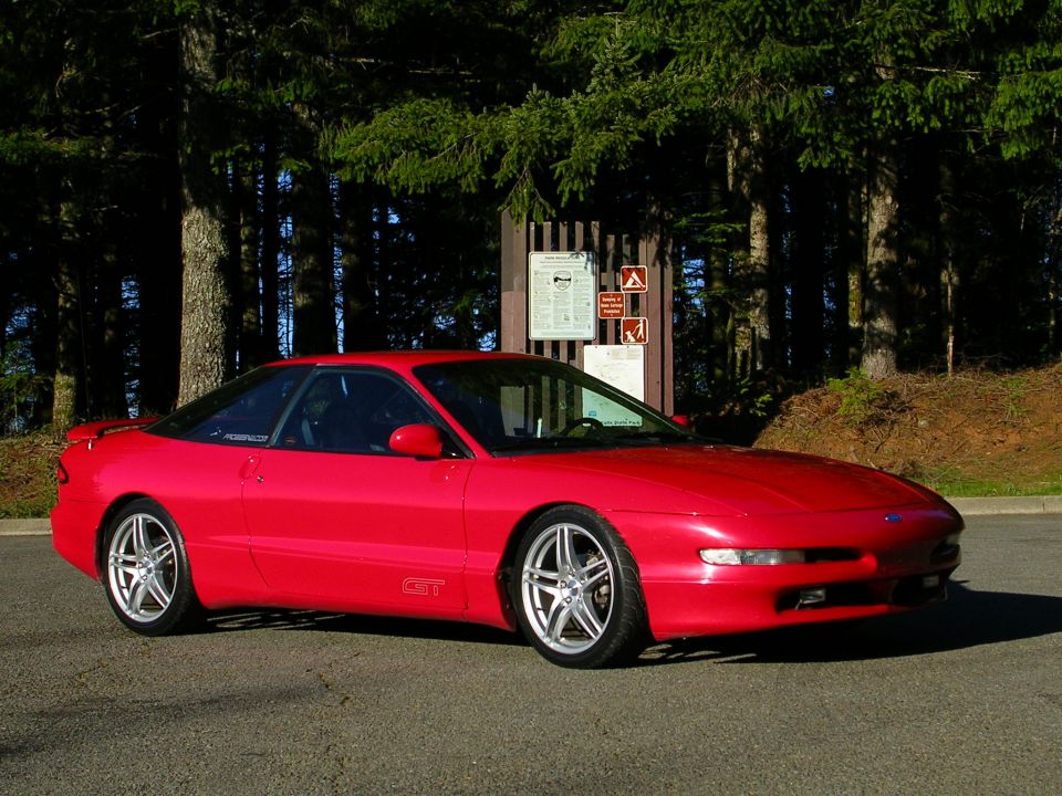
The 1993 model year brought the second-generation Ford Probe, a fully restyled front-wheel-drive coupe built on the Mazda GE platform and still sharing most of its mechanical hardware with the Mazda MX-6 and Mazda 626. The redesign replaced the first generation's pop-up headlamps with fixed lamps and changed the performance formula. The base 1993-1997 Probe used the Mazda FS 2.0-liter four-cylinder, rated at 115 horsepower and 124 lb-ft of torque for 1993-1994 and 118 horsepower and 127 lb-ft from 1995, and the GT replaced the earlier turbocharged four with the naturally aspirated Mazda KL 2.5-liter V6, a 24-valve four-cam engine rated at 164 horsepower, with 156 lb-ft of torque at launch, rising to 160 lb-ft during the run. The second-generation Probe was named Motor Trend Car of the Year for 1993. Trims included the base Probe and the GT, with an SE trim offered during the run. Like the first generation, the second-generation Probe was built at the Flat Rock, Michigan plant that also assembled the Mazda MX-6 and 626, by then operating as AutoAlliance International. Ford ended Probe production after the 1997 model year, and the front-drive coupe was not replaced by a like-for-like Ford model.
Other Ford Probe generations
The 1993-1997 Ford Probe at a glance
- Generation: second-generation Ford Probe, restyled front-wheel-drive coupe with fixed headlamps
- Platform: Mazda GE, shared with the Mazda MX-6 and Mazda 626
- Years: 1993 through 1997, the final Ford Probe generation
- Base engine: Mazda FS 2.0-liter four, 115 hp and 124 lb-ft for 1993-1994, 118 hp and 127 lb-ft from 1995
- GT engine: Mazda KL 2.5-liter V6, 24-valve, four-cam, 164 hp; 156 lb-ft at launch, rising to 160 lb-ft during the run
- Trims: base Probe and GT, with an SE trim during the run
- Recognition: Motor Trend Car of the Year for 1993
- Built at: Flat Rock, Michigan, by AutoAlliance International, alongside the Mazda MX-6 and 626; discontinued after 1997
Ford Probe 1993-1997 year by year
| Year | Ford Probe changes | Engines offered |
|---|---|---|
| 1993 | Second-generation Ford Probe arrives on the Mazda GE platform with fixed headlamps; named Motor Trend Car of the Year for 1993; the GT trades the turbo four for a 2.5 V6 | Mazda FS 2.0 four (base); Mazda KL 2.5 V6 (GT) |
| 1994 | The 1994 Ford Probe adds a passenger-side airbag with a redesigned dashboard, making dual front airbags standard across the line | Mazda FS 2.0 four; Mazda KL 2.5 V6 (GT) |
| 1995 | The 1995 Ford Probe continues with the base car and the GT; an SE trim is offered in the lineup | Mazda FS 2.0 four; Mazda KL 2.5 V6 (GT) |
| 1996 | The 1996 Ford Probe carries minor updates; the KL 2.5 V6 in the GT remained rated at 164 horsepower and 160 lb-ft of torque | Mazda FS 2.0 four; Mazda KL 2.5 V6 (GT) |
| 1997 | Final model year of the Ford Probe; production of the front-drive coupe ends after 1997 | Mazda FS 2.0 four; Mazda KL 2.5 V6 (GT) |
The Mazda GE platform and the 1993 redesign
The 1993-1997 Ford Probe was built on the Mazda GE platform, the same platform used by the second-generation Mazda MX-6 and the contemporary Mazda 626, and it shared most of its mechanical hardware with those cars. The 1993 redesign replaced the first generation's pop-up headlamps with fixed lamps and gave the Probe new body and interior styling. The Probe continued to be assembled at the Flat Rock, Michigan plant alongside the Mazda MX-6, by then operating as AutoAlliance International after Ford took a 50 percent stake in 1992. The second-generation Probe was named Motor Trend Car of the Year for 1993.
Engines of the 1993-1997 Ford Probe
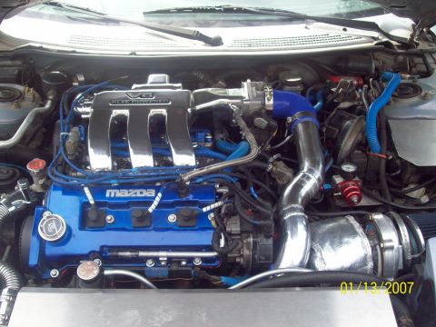
The base 1993-1997 Ford Probe used the Mazda FS 2.0-liter four-cylinder, rated at 115 horsepower and 124 lb-ft of torque for 1993-1994 and 118 horsepower and 127 lb-ft from 1995. The GT moved away from the first generation's turbocharged four and instead used the Mazda KL 2.5-liter V6, a 24-valve, four-camshaft engine rated at 164 horsepower, with torque of 156 lb-ft at launch, rising to 160 lb-ft during the run. The 2.5 V6 carried a variable-length intake system and was the Probe's top engine for the entire second generation. This 2.5 V6 is the Mazda-sourced six in the Probe, distinct from the Ford 3.0 Vulcan V6 that had been optional in the first-generation LX. Transmissions were a five-speed manual and a four-speed automatic depending on engine and trim.
The second-generation Ford Probe GT
The GT was the performance version of the 1993-1997 Ford Probe and used the naturally aspirated Mazda KL 2.5-liter V6 rated at 164 horsepower, with 156 lb-ft of torque at launch, rising to 160 lb-ft during the run, replacing the turbocharged four of the first-generation GT. The GT added four-wheel disc brakes, larger wheels and tires, and its own front and rear fascias. Because the second-generation GT used a V6 rather than a turbo four, it represents a different performance approach from the 1989-1992 GT, trading boosted four-cylinder torque for the smoothness and top-end of a four-cam V6.
Trims and the end of the Ford Probe
The 1993-1997 Ford Probe was sold as the base Probe and the GT, with an SE trim offered during the run. The base car and SE used the Mazda FS 2.0 four, and the GT used the Mazda KL 2.5 V6. Ford ended Probe production after the 1997 model year. The Probe was built at Flat Rock alongside the Mazda MX-6, and both front-drive coupes were dropped as the U.S. sport-coupe market contracted. Ford did not replace the Probe with a like-for-like front-drive coupe, and the rear-drive Mustang, which the Probe had once been planned to replace, continued in the lineup.
Frequently asked questions
What platform is the 1993-1997 Ford Probe?
The 1993-1997 Ford Probe is the second-generation car, built on the Mazda GE platform and sharing most of its mechanical hardware with the Mazda MX-6 and Mazda 626. The 1993 redesign replaced the first generation's pop-up headlamps with fixed lamps.
What engines did the 1993-1997 Ford Probe use?
The 1993-1997 Ford Probe used the Mazda FS 2.0-liter four (115 hp for 1993-1994, 118 hp from 1995) in the base car and the Mazda KL 2.5-liter V6 (164 hp) in the GT, with V6 torque of 156 lb-ft at launch, rising to 160 lb-ft during the run. The GT's 2.5 V6 was a 24-valve, four-camshaft engine, and it replaced the turbocharged four used in the first-generation GT.
Is the second-generation Probe GT a V6?
Yes. The 1993-1997 Ford Probe GT used the Mazda KL 2.5-liter V6 rated at 164 horsepower, a naturally aspirated 24-valve four-cam engine. This replaced the turbocharged four-cylinder used in the 1989-1992 first-generation GT.
Did the Ford Probe win Motor Trend Car of the Year?
Yes. The second-generation Ford Probe was named Motor Trend Car of the Year for 1993, the year the redesigned coupe arrived on the Mazda GE platform.
When did the Ford Probe end?
Ford ended Ford Probe production after the 1997 model year, closing out the second generation. The front-drive coupe was discontinued as the U.S. sport-coupe segment shrank and was not replaced by a like-for-like Ford coupe.
Sources
- Ford factory specification literature for the 1993-1997 Probe
- Wikipedia, Ford Probe (second generation)
- Mazda FS and KL-DE engine references
- Mazda MX-6 and 626 platform-sharing references (Mazda GE platform)
- AutoAlliance International / Flat Rock plant production history; Motor Trend Car of the Year 1993
Asked all the time
What platform is the 1993-1997 Ford Probe?
The 1993-1997 Ford Probe is the second-generation car, built on the Mazda GE platform and sharing most of its mechanical hardware with the Mazda MX-6 and Mazda 626. The 1993 redesign replaced the first generation's pop-up headlamps with fixed lamps.
What engines did the 1993-1997 Ford Probe use?
The 1993-1997 Ford Probe used the Mazda FS 2.0-liter four (115 hp for 1993-1994, 118 hp from 1995) in the base car and the Mazda KL 2.5-liter V6 (164 hp) in the GT, with V6 torque of 156 lb-ft at launch, rising to 160 lb-ft during the run. The GT's 2.5 V6 was a 24-valve, four-camshaft engine, and it replaced the turbocharged four used in the first-generation GT.
Is the second-generation Probe GT a V6?
Yes. The 1993-1997 Ford Probe GT used the Mazda KL 2.5-liter V6 rated at 164 horsepower, a naturally aspirated 24-valve four-cam engine. This replaced the turbocharged four-cylinder used in the 1989-1992 first-generation GT.
Did the Ford Probe win Motor Trend Car of the Year?
Yes. The second-generation Ford Probe was named Motor Trend Car of the Year for 1993, the year the redesigned coupe arrived on the Mazda GE platform.
When did the Ford Probe end?
Ford ended Ford Probe production after the 1997 model year, closing out the second generation. The front-drive coupe was discontinued as the U.S. sport-coupe segment shrank and was not replaced by a like-for-like Ford coupe.
Technical Reference
Member-uploaded diagrams & documents for this generation. AI-classified; community-verified where badged.
Wiring Diagrams (61)
- 2000 Mazda 626 2.5L Engine Performance Wiring Diagram - PCM Pins & O2 SensorsThis document is a scanned page from Mitchell Repair Information system wiring diagrams for a 2000 Mazda 626 ES, specifically Fig. 14: 2.5L Engine Performance Circuits (3 of 3). It shows wiring for the Powertrain…
- 2000 Mazda 626 ES 2.5L Engine Performance Wiring Diagram (2 of 3) - PCM & EGRThis document is page 2 of a three-page Mitchell Repair Information system wiring diagram set (Fig. 13) covering the engine performance circuits for a 2000 Mazda 626 ES with the 2.5L V6 engine. It shows PCM pinouts…
- 2000 Mazda 626 ES 2.5L Engine Performance Wiring Diagram - PCM Pinout (1 of 3)This document is page 1 of a three-page Mitchell Repair Information system wiring diagram set titled "2000 Mazda 626 ES, SYSTEM WIRING DIAGRAMS, Fig. 12: 2.5L, Engine Performance Circuits (1 of 3)." It shows the…
- Ford Probe PCM Connector Pinouts C248, C246, C247 - Wiring Diagram & Pin TableThis scanned page presents Ford Powertrain Control Module (PCM) connector pinout diagrams and tables, apparently from a Ford Probe wiring/EVTM manual. The main, clearly legible section covers connector C248, showing…
- 1993 Ford Probe PCM Connector Pinouts C247 C248 C249 - Wiring DiagramThis document is a scanned page of Ford Powertrain Control Module (PCM) connector pinout diagrams and tables covering three PCM connectors: C248, C247, and C249. For each connector, a physical connector face drawing is…
- 1996 Ford Probe Instrument Cluster Wiring Diagram - Tach, Oil Gauge, AlternatorThis scanned wiring diagram covers the instrument cluster circuits for a Ford Probe, specifically the tachometer, engine oil pressure gauge, ignition coil, distributor, powertrain control module (PCM), and integral…
- 1996 Ford Probe Instrument Cluster Wiring Diagram - Fuel & Temp Gauge CircuitsThis scanned wiring diagram covers the instrument cluster fuel and temperature gauge circuits for a Ford Probe (uploaded as a '1996 CLUSTER' page). It shows two power feeds: a METER 15A fuse (position 4) hot in…
- 1993-1994 Ford Probe 2.5L Cooling Fan Wiring Diagram - Relays, PCM & FusesThis is a scanned wiring diagram page for the electric engine cooling fan circuit of a 2.5L-engine vehicle (uploaded to a 1993 Ford Probe gallery; filename suggests a 1994 diagram). It shows power flowing from two…
- 1994 Ford Probe 2.5L Condenser Fan & A/C Clutch Wiring DiagramThis document is a factory-style wiring diagram for the condenser fan and A/C clutch circuits on a 2.5L engine (uploaded as a 1994 Ford Probe reference). Power comes from two sources: an AIR-COND 15A fuse in the…
- Ford Probe C241 Instrument Cluster Connector Pinout - Wire Colors & FunctionsThis document is a connector pinout reference for connector C241, the instrument cluster connector, showing a 14-pin connector face drawing with each cavity's circuit number and wire color labeled, followed by a table…
- Ford Probe Instrument Cluster Connector C240 Pinout - Wire Colors & FunctionsThis document is a connector pinout diagram for connector C240, which plugs into the instrument cluster. It shows a 16-pin connector drawing with each cavity numbered 1 through 16 and labeled with its circuit number…
- 1994 Ford Probe Instrument Cluster Wiring Diagram - ABS, TCIL, Anti-TheftThis scanned wiring diagram page (part of a multi-page instrument cluster set labeled '94 cluster') shows circuits for several Ford Probe instrument cluster indicators. Power comes from the interior fuse panel (ROOM…
- 1994 Ford Probe Instrument Cluster Wiring Diagram - Door Ajar & Washer FluidThis is one page of a multi-page factory-style wiring diagram covering the instrument cluster warning indicator circuits of a Ford Probe. The diagram shows three cluster indicators: the door ajar indicator, the fasten…
- 1994 Ford Probe Instrument Cluster Wiring Diagram - Warning Indicators & Air BagThis document is one page of a factory-style wiring diagram (EVTM) for the instrument cluster warning indicator circuits, uploaded as '94 cluster 4' for a Ford Probe. It shows the brake, hi beam, left turn, right turn…
- Ford Probe Instrument Cluster & VSS Wiring Diagram - 2.0L/2.5L SpeedometerThis document is one page of a factory-style wiring diagram covering the instrument cluster speedometer and vehicle speed sensor (VSS) circuits for a Ford Probe with either the 2.0L or 2.5L engine (legend: * = 2.0L, **…
- Ford Probe Instrument Cluster Wiring Diagram - Tachometer & Oil Pressure GaugeThis document is a scanned wiring diagram page covering the instrument cluster tachometer and oil pressure gauge circuits for a Ford Probe, with separate ignition input paths shown for the 2.0L engine (ignition coil…
- 1994 Ford Probe Instrument Cluster Wiring Diagram - Fuel & Temp Gauge CircuitsThis document is a scanned automotive wiring diagram covering the instrument cluster fuel and temperature gauge circuits, applicable to a vehicle offered with 2.0L and 2.5L engines (consistent with a mid-1990s Ford…
- 1994 Ford Probe PCM Wiring Diagram - TP Sensor, EVP Sensor & TCM CircuitsThis is one page of a multi-page factory-style wiring diagram set showing the Powertrain Control Module (PCM) circuits, apparently for a mid-1990s Ford Probe (uploaded as '94 ecu page 8'). The diagram shows the PCM…
- 1993-94 Ford Probe PCM Wiring Diagram - VAF Sensor, CPP & PNP Switch CircuitsThis scanned wiring diagram page (uploaded as '94 ecu page 7' for a Ford Probe) shows Powertrain Control Module (PCM) input circuits and related connections. The top of the page shows the Transaxle Control Module (TCM…
- 1993-94 Ford Probe Fuel Pump Relay & PCM Wiring Diagram - IFS Switch CircuitThis document is one page (page 6) of a multi-page wiring diagram set covering the fuel pump control circuit of a Ford Probe. It shows power arriving from splice S189 (page 25-1) via circuits 702 R/BK, supplying 12V in…
- 1994 Ford Probe PCM Wiring Diagram - CKP & ECT Sensor, TCM Circuits (Page 5)This document is one page of a multi-page Powertrain Control Module (PCM) wiring diagram for a Ford Probe. It shows circuits connecting the PCM to the Air Conditioner/Heater (page 54-4), Daytime Running Lamps (page…
- Ford Probe PCM Wiring Diagram - VRIS, IAC Valve, HO2S & Power Steering SwitchThis is one page of a factory-style wiring diagram set (uploaded as "94 ecu page 4") covering the Powertrain Control Module (PCM) circuits for a Ford Probe. It shows the wiring for VRIS Solenoid Valve #1 (circuit 713…
- 1994 Ford Probe PCM Wiring Diagram - HO2S, CANP & EGR Solenoid CircuitsThis document is one page of a multi-page factory-style wiring diagram covering the Powertrain Control Module (PCM) circuits of a Ford Probe. It shows the left Heated Oxygen Sensor (HO2S) with its shield grounds, the…
- 1994 Ford Probe V6 PCM Wiring Diagram - Fuel Injectors, Knock Sensor, GroundsThis scan is one page of a multi-page powertrain control module (PCM) wiring diagram, uploaded as "94 ecu page 2" for a Ford Probe. It shows the fuel injector circuits for a V6 engine: left fuel injectors #2, #4, #6…
- 1993-1994 Ford Probe PCM Power & Ground Wiring Diagram - ECU Page 1This is a scanned factory-style wiring diagram page covering the power supply and ground circuits for the Powertrain Control Module (PCM) system of a Ford Probe. It shows three power sources: the 15A ENGINE fuse in the…
- 1993 Ford Probe Windshield Wiper & Washer Switch Wiring DiagramThis is one page of a factory-style automotive wiring diagram covering the windshield wiper and washer circuit. It shows the combination switch assembly (with a note to 'SEE PAGE 149-5 FOR SWITCH TESTING'), which…
- 1993 Ford Probe Cooling Fan Circuit Wiring Diagram - Relays, PCM & FusesThis document is a scanned automotive wiring diagram showing the engine cooling fan circuit, filed by the uploader for a 1993 Ford Probe. Power feeds come from two sources: a 15A ENGINE fuse in the interior fuse panel…
- 1993 Ford Probe 2.5L A/C Condenser Fan & Clutch Circuit Wiring DiagramThis document is a scanned automotive wiring diagram for the A/C condenser fan and A/C clutch circuit on a vehicle with a 2.5L engine (uploaded as a 1993 Ford Probe reference). Power comes from an AIR-COND 15A fuse in…
- 1996 Ford Probe VRIS Solenoid Valve Wiring Diagram - C1008 C1009 C246 Pins 20/21This document is a cropped section of an automotive wiring diagram showing the circuits for two VRIS (Variable Resonance Induction System) solenoid valves, labeled VRIS Solenoid Valve #1 and VRIS Solenoid Valve #2…
- Ford Probe 2.5L PCM Connector C246 Pinout - Wire Colors & Circuit FunctionsThis document is a partial page from a Ford wiring reference showing connector C246, the Powertrain Control Module (PCM) connector for the 2.5L engine (Ford Probe application per the uploader's album). The top portion…
- 1996 Ford Probe 2.5L PCM Connector C248 Pinout - Wire Colors & FunctionsThis document is a connector pinout reference for connector C248 of the Powertrain Control Module (PCM) on a 2.5L engine (per the album context, a mid-1990s Ford Probe with the 2.5L V6). It shows a face view of the…
- 1996 Ford Probe 2.5L V6 Cooling Fan Wiring Diagram - Relays, PCM & FusesThis document is a factory-style wiring diagram for the electric engine cooling fan circuit on a 2.5L (V6) Ford Probe. It shows power feeds from two sources: a 15A ENGINE fuse in the interior fuse panel (hot in start…
- 1996 Ford Probe Oxygen Sensor, CKP & Knock Sensor Wiring Diagram (PCM)This is a scanned engine-control wiring diagram page showing the crankshaft position (CKP) sensor, four heated oxygen sensors (HO2S), and the knock sensor (KS) circuits connecting to the powertrain control module (PCM…
- Ford Probe 2.5L PCM Connector C247 Pinout - Wire Colors & Circuit FunctionsThis document is a connector pinout reference for connector C247, the Powertrain Control Module (PCM) connector on a Ford Probe with the 2.5L engine. The top portion shows a physical drawing of the 22-cavity connector…
- 1996 Ford Probe 2.5L PCM Connector C245 Pinout Diagram - Wire Colors & FunctionsThis document is a connector pinout diagram and legend table for the Powertrain Control Module (PCM) connector labeled C245 on a Ford Probe with the 2.5L engine. The top portion shows a face view of the 28-position PCM…
- 1996 Ford Probe 2.5L PCM Connector C245 Pinout - Automatic Transaxle WiringThis document is a connector pinout diagram and table for connector C245 on the Powertrain Control Module (PCM) of a vehicle equipped with the 2.5L engine and automatic transaxle. The diagram shows a 16-pin PCM…
- Ignition Coil, Distributor & Tach Signal Wiring Diagram - Fuse #7 CircuitThis document is a wiring diagram of an ignition/tachometer circuit showing how the tachometer signal is routed from the ignition system to the instrument cluster. A BRN (brown) wire runs from the TACH (instrument…
- Ford Probe PCM Power Relay & FPRC Solenoid Wiring Diagram - ECM CircuitThis document is a scanned page from a Ford wiring diagram (EVTM-style) showing power distribution and control circuits for the Powertrain Control Module (PCM) on a Ford Probe. It depicts the PCM power relay located in…
- Ford Probe Fuel Pump Relay & Inertia Switch Wiring Diagram - PCM/DLC CircuitThis document is a factory-style wiring diagram covering the fuel pump and fuel gauge sender circuit for a Ford Probe, along with related Powertrain Control Module (PCM) and Data Link Connector (DLC) wiring. It shows…
- Ford Probe PCM Wiring Diagram - HO2S, EGR & Canister Purge Solenoid CircuitsThis document is a scanned page from a Ford Probe wiring diagram covering the Powertrain Control Module (PCM) and emissions-related circuits. It shows the left Heated Oxygen Sensor (HO2S), Canister Purge (CANP)…
- Ford Probe V6 PCM & Fuel Injector Wiring Diagram - Knock Sensor, GroundsThis is a page from a Ford factory-style wiring diagram covering the fuel injector and Powertrain Control Module (PCM) circuits, apparently for a V6 engine (six injectors). Power from connector C149 (page 25-1) feeds…
- Ford Probe Oxygen Sensor, CKP & Knock Sensor Wiring Diagram - PCM CircuitsThis document is a factory-style engine management wiring diagram showing the connections between the powertrain control module (PCM, labeled 'SOLID STATE' at the bottom, with the left-margin label cut off but reading…
- 1993 Ford Probe Power Door Lock Wiring Diagram - Relay, Motors & SwitchesThis document is a scanned power door lock system wiring diagram, uploaded to a 1993 Ford Probe gallery. It shows the complete power door lock circuit: power feeds from the interior fuse panel (a 30A DOOR LOCK fuse hot…
- Ford Probe 2.5L PCM Connector C246 Pinout - Wire Colors & Circuit FunctionsThis document is a factory-style connector pinout page for connector C246, the Powertrain Control Module (PCM) connector on the 2.5L engine (Ford Probe application per uploader). It shows a diagram of the 26-pin PCM…
- 1997 Ford Probe 2.5L Grounds Wiring Diagram - G104 G105 G106, PCM & HO2SThis is page 10-9, "GROUNDS," from the 1997 Ford Probe electrical wiring diagram manual, covering the 2.5L engine ground distribution circuit. The diagram traces ground wiring from major components — fuel pump module…
- Quad Headlight Wiring Diagram - Relay Terminals 30/85/86/87 (Ford Probe)This document is a hand-drawn/computer-illustrated wiring diagram titled 'Quad Headlight Wiring Diagram,' showing how to wire separate low beam and high beam headlight bulbs through an automotive relay. The diagram…
- Ford Probe Instrument Illumination Wiring Diagram 71-2 - Dimmer, Radio, EQThis is a screenshot from Ford's Technical Service Publications EVTM (Electrical and Vacuum Troubleshooting Manual) software showing wiring diagram section 71-2, Instrument Illumination. The diagram illustrates the…
- 1996 Ford Probe 2.5L PCM Connector C247 Pinout - Wire Colors & FunctionsThis document is a screenshot from Ford's EVTM (Electrical and Vacuum Troubleshooting Manual) Technical Service Publications software showing connector C247, the Powertrain Control Module (PCM) connector for the 2.5L…
- 1993 Ford Probe PCM Connector Pin Chart (Part 2, M/T) - Pinout & Wire ColorsThis document is a screenshot of an ALLDATA Pro page titled 'PCM Connector Pin Chart (Part 2, M/T)', showing a Powertrain Control Module (PCM) connector pinout table for a manual-transmission application. It is filed…
- MegaSquirt MS I 2.2 Ignition Wiring Sketch - 1995 Ford Probe (Hand-Drawn)This is a hand-drawn (pen on paper) wiring diagram documenting a MegaSquirt standalone engine management installation, labeled "MS I 2.2" (MegaSquirt I, version 2.2 board) with the annotation "inverted: NO." The sketch…
- MSD 6A/6AL Wiring Diagram - 1996 Mazda KL V6 (Ford Probe GT) Failed OEM IgnitorThis is a color wiring diagram showing how to install an MSD 6A/6AL ignition box on a 1996 Mazda KL-series V-6 engine when the OEM ignitor has failed, using an external coil. The diagram, credited to Eric Leska…
- Ford Probe Door Lock Wiring Diagram - Single Wire Relay & Resistor Alarm HookupThis wiring diagram from the Alarmtek Archives shows how to interface a car alarm or keyless entry system with the Ford Probe's single-wire door lock system. The diagram depicts two standard 30-amp automotive relays…
- Ford Probe Halo Ring Headlight Wiring Diagram - H4 Harness & Side Marker TapThis is a hand-drawn wiring diagram (created in a basic image editor) showing how to wire aftermarket headlights with halo rings ('Rings') to a vehicle's stock or H4 headlight harness. The main drawing shows two round…
- Simple Auxiliary Lights Wiring Diagram - Battery, Fuse, Switch to Lights & GroundThis is a simple hand-drawn (computer-sketched) wiring diagram showing how to wire a basic auxiliary light circuit, uploaded to the gallery of a 1993 Ford Probe. The diagram shows five labeled elements connected in…
- MSD External Coil HEI Module Wiring Diagram - 1994 MX6 V6 Distributor IgnitionThis is a hand-annotated wiring diagram titled "MSD External Coil HEI Module Diagram," created by user "bencollinz" on 1/28/05 for a 1994 MX6 V6. It shows how to wire an MSD Multiple Spark Discharge ignition box…
- 1994 Ford Probe GT MSD External Coil HEI Module Wiring DiagramThis is a hand-annotated wiring diagram titled "MSD External Coil HEI Module Diagram," drawn by community member "bencollinz" and dated 1/28/05, labeled for a 1994 PGT MTX (Probe GT, manual transmission). It shows how…
- Kyotto KD20C10AX Solid State Relay Meth Pump Wiring - PNP Pulse Inverter SketchThis document is an annotated photograph serving as a hand-drawn wiring diagram for controlling a methanol (meth) injection pump using a solid state relay. The central component is a KYOTTO KD20C10AX AC solid state…
- MegaSquirt Pressure Sender Wiring Diagram - Add Autometer Gauge Input to MSThis is a hand-drawn wiring diagram showing how to add an electrical pressure gauge (oil or fuel pressure sender) to a MegaSquirt (MS) engine management system so its reading can be displayed on tuning software. The…
- 1993 Ford Probe Door Popper Wiring Diagram - Keyless Entry Relay Setup (MAC1)This is a hand-drawn (computer-sketched) wiring diagram, credited to "MAC1," showing how to wire aftermarket door poppers (solenoids that pop the doors open) into a vehicle's factory keyless entry and door lock system…
- GM HEI Module Conversion Wiring - Pin W, C, G, B Connections (1994 Ford Probe)This document is an annotated photograph showing how to wire a GM HEI ignition module for an ignition conversion. The white HEI module is shown resting on top of a printed factory wiring diagram, with blue and red…
- Hand-Drawn Wiring Diagram Sketch - Horn/Pump Relay Circuit (Ford Probe Gallery)This image is a photograph of a hand-drawn wiring diagram sketched in pen on a sheet of white paper, resting on a wooden table. The photo is significantly out of focus, making nearly all handwritten labels unreadable…
Schematics (25)
- Tachometer Output from Coil Negative - 1N4004 Diode Rev Counter SchematicThis document is a simple electronics schematic showing how to create a tachometer (rev counter) output signal from ignition coil negative (-ve) terminals, typically when converting to a coil-per-cylinder or…
- MegaSquirt MS2 VR/Tach Input Circuit Schematic - 4N25 Opto & MC34072AP DebugThis document is an annotated electronic schematic (filename 'ms2 fail.jpg') showing a tach/ignition input-conditioning circuit, apparently from a MegaSquirt-style engine controller. It includes an opto-isolator (U3…
- Exhaust Venturi Turbo Flow Schematic - Intake Air, Fuel & Exhaust Gas DiagramThis document is a conceptual schematic (not a text-based reference) showing gas flow paths through an engine system. Only three text labels appear: FUEL, INTAKE AIR, and EXHAUST GAS. The drawing depicts a…
- Garrett T3 60 Trim Turbo Compressor Map with Plotted Operating LineThis document is a compressor map for a Garrett T3 turbocharger with a "60" trim compressor wheel. The map plots pressure ratio (P2C/P1C, from 1.00 to 3.00) on the vertical axis against corrected air flow…
- Ford Probe ECU Board U6 MAX232-Type IC Pin Voltages - Good Board ReferenceThis document is an annotated electronic schematic showing a 16-pin serial line driver/receiver IC labeled U6 (with pin functions C1+, V+, C1-, C2+, C2-, V-, T2OUT, R2IN, R2OUT, T2IN, T1IN, R1OUT, R1IN, T1OUT, GND, Vdd…
- U6 Chip Serial Interface Schematic & Test Voltages - Shorted Board DiagnosisThis document is a partial electronic schematic, annotated by hand, focused on the U6 chip of a circuit board (an RS-232 level converter type IC with C1+/C1-, C2+/C2-, V+, V-, T1IN/T1OUT, T2IN/T2OUT, R1IN/R1OUT…
- 68HC908GP32 Microcontroller Pinout with 5V & GND Annotations - Ford Probe SchematicThis document is a cropped schematic excerpt showing the complete 40-pin pinout of a Motorola/Freescale 68HC908GP32 microcontroller, labeled U1. All 40 pins are shown with their signal names: power and oscillator pins…
- MegaSquirt II Power Supply & CPU Clock Schematic with Voltage Test ReadingsThis document is a schematic of the power supply and CPU clock sections of a MegaSquirt-II (MSII) engine management controller board, annotated by hand in red with measured voltage readings, apparently for…
- MegaSquirt DB37 & DB9 Connector Schematic - Pinout, Jumpers & Test VoltagesThis document is a schematic page titled "Megasquirt - Connector," showing the connector and serial-communication section of a MegaSquirt DIY engine management (EFI) controller. It depicts U6, a 16-pin RS-232…
- Megasquirt MSII Power Supply Schematic - LM2937ET-5.0 5V Regulator & CPU ClockThis document is a power supply schematic page (apparently from a Megasquirt-style engine controller board) with handwritten troubleshooting voltage measurements marked in red. The printed circuit shows a 12V raw input…
- MegaSquirt DB37 Connector & DB9 Serial Schematic with U6 Voltage Test PointsThis document is a page from a MegaSquirt DIY engine management (EFI controller) schematic, specifically the "Megasquirt - Connector" sheet. It shows the serial communications circuit built around U6 (a 16-pin RS-232…
- Twincharged Setup Schematic - M62 Supercharger + T66 Turbo Plumbing DiagramThis document is a hand-drawn schematic (uploaded as "twincharged.jpg") illustrating a custom "twincharged" forced-induction setup combining a supercharger and a turbocharger. The drawing shows an engine with plumbing…
- 1993 Ford Probe Ignition System Schematic - Distributor, ICM & PCM WiringThis document is a screenshot of an ALLDATA (alldatapro.com) ignition system schematic, uploaded as a reference for a 1993 Ford Probe. The diagram shows the internal layout of the distributor assembly, which houses the…
- Ford Probe ECT/CLT Sensor Circuit Mod Schematic - Before/After Comparator SketchThis is a hand-drawn engineering sketch, drawn on the back of (or over) a printed schematic sheet dated Sunday, March 27, 2011 (Rev 3.0, Sheet 6, name partially reading "...Grippo"). It documents a before/after…
- Ford Probe Cooling Fan Relay Comparator Mod Schematic - Denso 179700-0220 ECTThis is a hand-drawn electronic schematic comparing a cooling fan control comparator circuit "BEFORE" and "AFTER" a modification. Both sides show an op-amp comparator circuit powered by VCC 4.8V with a BIAS resistor of…
- Ford Probe DIY High-Speed Fan Trigger Circuit - LM393 Comparator SchematicThis is a hand-drawn electronic schematic sketched in pen (with some traces highlighted in yellow) over a faint printed factory wiring diagram, uploaded to a 1993 Ford Probe gallery. The circuit is built around an…
- 60-2 Crank Trigger Wheel Diagram - Tooth Positions A/B/C, VR Sensor AlignmentThis hand-annotated schematic shows a 60-2 (60-minus-2) crankshaft trigger wheel and how its teeth relate to ignition/timing trigger positions. The wheel diagram is labeled with tooth numbers around its circumference…
- 60-2 Crank Trigger Wheel Diagram - VR Sensor & Tooth Alignment (Ford Probe)This is a hand-annotated schematic drawing of a 60-2 crankshaft trigger wheel (60 tooth positions with 2 teeth missing) used for engine position sensing with a VR (variable reluctance) sensor. The drawing shows the…
- Ford Probe VRIS Switching Valve Diagram - Torque vs RPM Intake OperationThis schematic illustrates the operation of a Variable Resonance Induction System (VRIS) intake manifold with two switching valves (A and B). The top portion shows a cutaway drawing of the intake manifold identifying…
- V-12 Engine Transparent 3D Cutaway Rendering - Internal Components ViewThis image is a computer-generated (CAD-style) transparent rendering of a V-configuration piston engine, apparently a V-12 based on the upload filename and the number of visible cylinders arranged in two banks. The…
- Ford Probe Supercharger Intake Layout Schematic - SC/IM, TB, VAF, Filter DiagramThis is a simple hand-drawn digital schematic (appears to be created in a basic paint program) illustrating an engine intake layout, apparently for a supercharger/intake manifold arrangement. The upper portion shows a…
- Timing Chain & Sprocket Layout 3D Diagram - 1994 Ford Probe Gallery UploadThis document is a computer-generated 3D illustration (CAD-style rendering) of a timing chain drive assembly, uploaded to a 1994 Ford Probe gallery. The image shows a single timing chain (rendered in tan/gold) wrapped…
- V-12 Engine Cutaway 3D Render - Overhead View of Pistons, Cams & Belt DriveThis document is not a text-bearing schematic but a 3D rendered illustration of a large V-configuration engine, apparently a V-12 based on the filename and the number of visible cylinders per bank. The render uses a…
- 1994 Ford Probe Intake Manifold Sketch - Long & Short Runner Ports, Throttle BodyThis document is a hand-drawn pencil sketch (schematic-style illustration) of an automotive intake manifold, uploaded as "intake.jpg" to a 1994 Ford Probe gallery. The drawing shows a multi-runner intake manifold in…
- Simple Home Network Diagram - ADSL Modem, Wireless Router, Wired & Wireless PCsThis document is not an automotive schematic; it is a simple home computer networking diagram titled "Simple Home Networking and Internet Connection Sharing." It depicts the rear panel of a wireless router (with two…
Brochures & Literature (6)
- 3-Position Rotary Selector Switch – Contact Positions #1 & #2 DiagramThis is a seller's product photo (marked "US SELLER") of a panel-mount 3-position rotary selector switch, not a printed automotive reference document. The main image shows a hand turning the black selector knob of a…
- 3-Position Rotary Selector Switch - Contact Diagram (#1/#2 Circuits)This image is a seller's product photo (marked "US SELLER") of a panel-mount 3-position rotary selector switch, not a printed automotive reference document. The main photo shows a hand turning the black lever-style…
- Pyramid Power PBIN-3 1000W Amplifier Installation Wiring Kit - Contents ListThis document is the retail packaging label for a Pyramid Power PBIN-3 Amplifier Installation Wiring Kit rated for 1000 watts. The label lists the complete contents of the kit in a table format: a 20-foot red power…
- Ford Probe Brochure Page 18 - Probe Power: DOHC 24-Valve V6 & I-4 EnginesThis is page 18 of a Ford Probe sales brochure, titled "Probe Power." The page pairs marketing text with a large photograph of the Probe's engine bay, prominently showing the V6 engine with its "V6" and "DOHC 24-VALVE"…
- Ford Probe GT Brospeed/Bosal Headers Dyno Test Write-Up (1998) - Page 2This document is page 2 of 6 of a printed web page (http://www.mtco.com/~westcj/Brian/bosal.htm, printed 10/27/2001) describing dyno testing of Brospeed headers (a subsidiary of Bosal USA, Inc.) on a Ford Probe GT…
- 1993 Ford Probe GT Review & Specs - Automobile Magazine Buying & Leasing '95This is a two-page spread from Automobile Magazine's "Buying & Leasing '95" issue covering the 1993 Ford Probe GT as part of a long-term (Four Seasons) test review. The article includes full factory specifications: a…
Service Procedures (4)
- 1993 Ford Probe Two Speed Cooling Fan Circuit Operation - 2.0L & 2.5LThis document is a 'How The Circuit Works' description for the Two Speed Cooling Fan circuit, applicable to vehicles with 2.0L and 2.5L engines (consistent with the uploader's Ford Probe). It explains that battery…
- Ford Probe Control Module Bench Test Diagram - Ohmmeter & Test Light HookupThis document is a labeled illustration showing a bench-test setup for a control module. The diagram depicts a control module connected to a 12 volt battery, a test light, and an ohmmeter. Callout labels identify the…
- Ford T92C-6000-AH Breakout Box Adapter Instructions - 1993 Probe 2.0L & 2.5LThis document is an instruction sheet for the Ford T92C-6000-AH Breakout Box Adapter, stated as applicable to 1993 Probe 2.0L and 2.5L engines. It explains how to connect the adapter between the vehicle wiring harness…
- Turbosmart Boost Tee Instructions - Gate System Removal & TroubleshootingThis document is page 3 of 4 of a Turbosmart Boost Tee manual boost controller instruction sheet (PDF filename INST_BoostTee[1].pdf, viewed in Adobe Reader). The visible section, titled 'Important Notes on Gate System…
Torque Specs (1)
- Connecting Rod Bolt Torque Specs & Clearances - 8740 Cap Screw Instruction SheetThis document is a photographed page from an aftermarket connecting rod installation instruction sheet, shown alongside two twelve-point connecting rod cap screws (bolts) laid on the paper. The page warns about…
Vacuum Routing (9)
- 1995 Ford Probe Multi-Stage Boost Control Vacuum Routing Diagram - Wastegate SetupThis is a hand-drawn vacuum/pressure hose routing diagram uploaded as "multi stage boost.jpg," illustrating a custom multi-stage boost control setup on a turbocharged vehicle (claimed to be a 1995 Ford Probe). The…
- 1995 Ford Probe Multi-Stage Boost Control Vacuum & Wiring Diagram - Profec BThis is a hand-drawn (computer-sketched) vacuum routing and wiring diagram showing a custom multi-stage turbo boost control setup, uploaded to a 1995 Ford Probe gallery. A legend indicates blue lines are electrical…
- 1995 Ford Probe Vacuum Hose Routing Diagram - VRIS, EGR & Solenoid ValvesThis document is an annotated engine vacuum routing diagram, uploaded for a 1995 Ford Probe. It is a line drawing of the engine's intake area with color-coded vacuum hoses and labeled callouts identifying vacuum system…
- 1995 Ford Probe Vacuum Hose Routing Diagram - VRIS, EGR & Purge SolenoidsThis document is an annotated (modified) vacuum hose routing diagram uploaded for a 1995 Ford Probe. It is a perspective drawing of the engine's intake manifold area with color-coded vacuum lines and callout labels…
- 1994 Ford Probe V6 Vacuum Hose Routing Diagram - VRIS, EGR & Purge SolenoidsThis document is a color-coded vacuum hose routing diagram for an automotive engine, uploaded as applying to a 1994 Ford Probe. The diagram shows an isometric illustration of the engine's intake manifold and vacuum…
- 1996 Ford Probe Vacuum Hose Routing Diagram - EGR, EVAP & VRIS LinesThis document is an annotated photograph serving as a vacuum routing diagram. It shows an actual vacuum hose harness laid out flat, with each hose and component labeled with text callouts. Labeled connections include…
- 1994 Ford Probe Vacuum Hose Routing Diagram - VRIS, EGR & Purge SolenoidsThis document is a scanned engine vacuum hose routing diagram uploaded for a 1994 Ford Probe. It is a line-art illustration of the engine (viewed from above/front) showing the routing of vacuum hoses among emission and…
- 1993 Ford Probe Compound Turbo & Intercooler Plumbing Routing DiagramThis document is not a printed reference page but a modified photograph of a front-wheel-drive engine bay (consistent with the uploader's Ford Probe) with hand-drawn overlay lines illustrating a planned turbocharger…
- Ford Probe V6 Compound Turbo/Supercharger Plumbing Sketch - Engine Bay DiagramThis document is not a printed factory diagram but a photograph of an engine bay — a transverse V6 with the upper intake removed, showing three exposed intake ports — with a hand-drawn boost-plumbing schematic sketched…
Exploded Parts (2)
- Exhaust Manifold & Turbocharger Exploded Diagram with Torque Specs (AC210648AB)This document is an exploded parts diagram of an exhaust manifold and turbocharger assembly on a four-cylinder engine, drawing reference AC210648AB. It shows the exhaust manifold, exhaust manifold gasket, heat…
- 1993-94 Ford Probe Engine Bay Component Location Diagram - Relays, Fans, GroundsThis document is a screenshot of an electronic service publication (file ERUCM187.GUI) showing an engine compartment component location diagram, apparently for a Ford Probe (uploaded to a 1993 Probe gallery, filename…
Data/Spec Plates (12)
- Dodge SRT-4 Stage 3 Dynapack Dyno Sheet - 412.9 lb-ft Torque & AFR GraphThis document is a chassis dynamometer results sheet produced on a Dynapack dyno at Xact Dyno of Tempe, Arizona, dated 26-Apr-2007 (12:10:42). The run ID is "KOVACH STG3 SRT4-2" in the folder "UMS." The sheet shows two…
- SRT-4 Stage 3 Dyno Sheet - 22 psi Boost Curve, Xact Dyno Dynapack 2007This is a chassis dynamometer printout from Xact Dyno (Tempe, Arizona), produced on Dynapack chassis dynamometer software (RHAS-SP V1.3-03E, 4WD - Motor Vehicle 2000+4000). The sheet plots manifold pressure (MAP)…
- Dodge SRT-4 Stage 3 Dyno Sheet - 358.7 HP / 412.9 lb-ft Dynapack Results 2007This document is a chassis dynamometer results sheet produced on a Dynapack chassis dynamometer at Xact Dyno in Tempe, Arizona, dated 26-Apr-2007. The header reads "RHAS-SP V1.3-03E (4WD - Motor Vehicle 2000+4000) -…
- Ford Probe GT Car and Driver Test Specs - 2.5L V6, 0-60, Quarter Mile ResultsThis is a scanned specifications and test-results page from Car and Driver magazine covering the Ford Probe GT (second-generation, tested as an early/pre-production example with an estimated $19,000 as-tested price and…
- Bosal Headers vs Stock Manifolds Dyno Data - Torque & HP Comparison ChartThis is page 4 of a 6-page printout (dated 10/27/2001, from http://www.mtco.com/~westcj/Brian/bosal.htm) comparing exhaust header performance on a dynamometer. It is titled 'Bosal Headers' with a section heading 'Stock…
- 1996 Ford Probe Dynojet Dyno Sheet - 178 HP / 162 ft-lb with AEM O2 DataThis document is a Dynojet Research chassis dynamometer printout from Bristol Dyno (860 282 2248) / Victor Research (860 282 7223), dated 4/11/2006, comparing two dyno runs on the same vehicle. Run DYNORUN_056.drf…
- 1996 Ford Probe Dynojet Dyno Chart - 189 hp / 165 ft-lb Dyno Run ResultsThis document is a photographed printout of a Dynojet Research chassis dynamometer graph produced at Bristol Dyno (860 282 2248) / Victor Research (860 282 7223), comparing two dyno runs of the same vehicle. The chart…
- 1995 Ford Probe Dynojet Dyno Sheet - 147 HP / 155 ft-lb Runs, Modacar 2006This document is a scanned Dynojet Research chassis dynamometer printout produced at Modacar Auto Accessories, dated January 28, 2006. It charts six dyno runs for a vehicle attributed to "Jarrod Silvius," plotting…
- 1995 Ford Probe Dyno Sheet - Dynojet Results 147.51 HP / 155.24 ft-lbs (2006)This document is a scanned Dynojet Research chassis dynamometer results sheet printed by Modacar Auto Accessories, dated 1/28/2006. It overlays six dyno pulls attributed to Jarrod Silvius, plotting horsepower and…
- 1995 Ford Probe Dynojet Dyno Sheet - 145 HP After 64mm Throttle Body (2006)This document is a scanned Dynojet Research chassis dynamometer results sheet printed by Modacar Auto Accessories, uploaded to the gallery of a 1995 Ford Probe. A handwritten note reads "After 64TB," indicating this…
- 1995 Ford Probe Dyno Sheet - 145 HP After 64mm Throttle Body (Dynojet 2006)This document is a Dynojet Research chassis dynamometer printout produced at Modacar Auto Accessories, showing three back-to-back dyno runs performed on 1/28/2006 for "jarrod silvius" (files run 2_001.drf, run…
- 1995 Ford Probe Dyno Sheet - Baseline Runs Before 64mm Throttle Body (147 HP)This document is a Dynojet Research chassis dynamometer printout from Modacar Auto Accessories, dated January 28, 2006, uploaded to the gallery of a 1995 Ford Probe. It records three back-to-back dyno runs (files…
Blueprints (7)
- Hub Spacer Ring Blueprint - Ø77.75 OD x Ø72.00 ID x 6.35 Thick (Ford Probe)This document is a CAD-style blueprint (mechanical drawing) of a thin circular ring, uploaded as 'hub-space.JPG' and apparently depicting a hub-centric spacer ring. The drawing shows three views: a small…
- 1993 Ford Probe Spacer Blueprint - 25mm OD x 10.4mm ID x 12mm DrawingThis document is a simple CAD-style blueprint (mechanical drawing) of a small cylindrical spacer or bushing. Three views are shown: an isometric view at the upper right, a front (face) view at the lower left with…
- 1993 Ford Probe Caliper Bracket Blueprint - Dimensioned Adapter Plate DrawingThis document is a dimensioned mechanical blueprint (three-view drawing plus an isometric detail at SCALE 0.5) of a flat mounting bracket, filed by the uploader as a 'cal-bracket' (caliper bracket) for a 1993 Ford…
- Pinewood Car AutoCAD LT Blueprint Screenshot - Sports Car Multi-View DrawingThis document is a screenshot of AutoCAD LT with a drawing file named "pinewood car1.dwg" (stored on drive H:) open in Model space. The drawing shows multiple orthographic views of a low-slung sports car body: a…
- AutoCAD LT Car Body Blueprint Screenshot - Multi-View Sports Car CAD DrawingThis document is a screen capture of AutoCAD LT running on Windows XP, displaying an open drawing file named "pinewood car1.dwg" stored on drive H:. The drawing is a multi-view wireframe blueprint of a sports car body…
- Race Track Site Plan Blueprint - 2.23 Mile Circuit Layout, Turn Radii & PaddockThis document is a scanned site plan / blueprint of a road racing facility, not a vehicle wiring or fuse diagram. It shows a 2.23-mile Phase 1 race track with 15 numbered turns, each annotated with a curve callout…
- 1993 Ford Probe Custom Box Enclosure Blueprint - Front Piece & Side Panel LayoutThis document is a simple construction blueprint/sketch, uploaded to a 1993 Ford Probe gallery, showing how to build a rectangular box-style enclosure from flat panels. On the left is a three-dimensional isometric…
Manual Pages (1)
- Mazda L3 Turbo (L3 with TC) Fuel System Diagram - High Pressure Fuel Pump & RelaysThis scanned service manual page is titled "FUEL SYSTEM [L3 WITH TC]" and presents the "Fuel System Structural View [L3 With TC], Engine Compartment Side." It is an illustrated diagram of the engine bay showing the…
The wall · registered 1993–1997 Probes
Sorted by depth of documentation. Click any vehicle to open its permanent record.