Ford Probe Cooling Fan Relay Comparator Mod Schematic - Denso 179700-0220 ECT
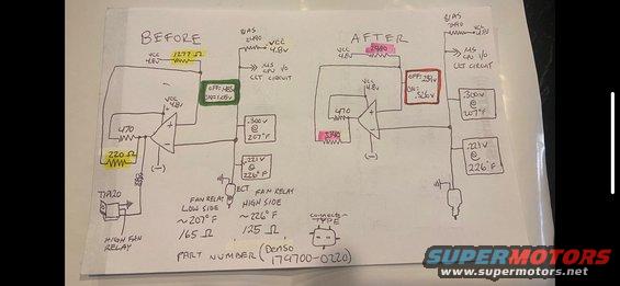
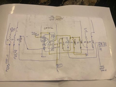
Hand-drawn before/after circuit schematic of an op-amp fan-relay control with voltage and resistance annotations.
This is a hand-drawn electronic schematic comparing a cooling fan control comparator circuit "BEFORE" and "AFTER" a modification. Both sides show an op-amp comparator circuit powered by VCC 4.8V with a BIAS resistor of 2490 feeding a signal labeled "MS CPU I/O CLT CIRCUIT" (apparently a MegaSquirt-style coolant temperature input). In the BEFORE circuit, resistor values of 1277 Ω, 470, and 220 Ω produce comparator switching thresholds of OFF: .483v / ON = 1.05v. In the AFTER circuit, the resistors are changed to 2980 and 3340 (with the 470 retained), yielding thresholds of OFF: .239v / ON = .326v. Reference voltages from the ECT (engine coolant temperature) sensor are noted as .300v @ 207°F and .221v @ 226°F. The BEFORE side shows a TIP120 transistor driving the HIGH FAN RELAY, with fan relay trigger points listed: Fan Relay Low Side ~207°F (165 Ω) and Fan Relay High Side ~226°F (125 Ω). A connector type sketch is included, and the ECT sensor is identified by part number Denso 179700-0220. The document lets a reader understand how resistor changes shift the fan-on/fan-off voltage thresholds relative to coolant temperature.
Is this accurate? Sign in to help verify it.
Frequently asked questions
- What are the fan relay trigger temperatures shown in this schematic?
- Fan relay low side triggers at approximately 207°F (165 Ω) and fan relay high side at approximately 226°F (125 Ω).
- What ECT sensor voltages correspond to the fan trigger temperatures?
- The schematic notes .300v @ 207°F and .221v @ 226°F at the ECT sensor input.
- What resistor values were changed between the BEFORE and AFTER circuits?
- The BEFORE circuit uses 1277 Ω and 220 Ω resistors (with a 470 and BIAS 2490); the AFTER circuit changes these to 2980 and 3340 while keeping the 470 and BIAS 2490.
- How did the comparator switching thresholds change after the modification?
- BEFORE: OFF = .483v, ON = 1.05v. AFTER: OFF = .239v, ON = .326v.
- What part number is referenced for the sensor?
- The part number shown is Denso 179700-0220, with a 3-pin connector type sketched.
Comments
More from this build









No comments yet.