1995 Ford Bronco TR Sensor (MLPS) Testing - E4OD/4R70W Pinout & Ohm Values
Transmission Range (TR) sensor component testing: ohmmeter resistance values per shift position for W/E4OD and W/4R70W, with circuit numbers, wire colors, and schematic.
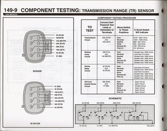
This is page 149-9 of a Ford component testing reference, titled 'Component Testing: Transmission Range (TR) Sensor' for the 1995 Bronco. It covers bench/continuity testing of the TR sensor (also known as the MLPS) used with the E4OD and 4R70W automatic transmissions. The left side shows two 8-pin connector pinout diagrams — one for the E4OD and one for the 4R70W — with circuit numbers and wire colors for each terminal (e.g., 32 R/LB, 463 R/W, 140 BK/PK, 359 GY/R, 298 P/O, 199 LB/Y, 57 BK, and 33 W/PK on the 4R70W). The main table gives the component testing procedure: which terminal pairs to connect an ohmmeter or self-powered test lamp to for the Transmission Circuit, Backup Lamp Circuit, Starter Relay Circuit, and 4X4 Low-Neutral Sense Circuit, and the expected readings in each gear position (Park, Reverse, Neutral, Drive, Second, First). For example, the transmission circuit (359 GY/R and 199 LB/Y) should read 3770–4607 ohms in Park down to 78–95 ohms in First. A schematic at the bottom shows the internal rotary switch contacts and resistor network with all circuit numbers and wire colors labeled.
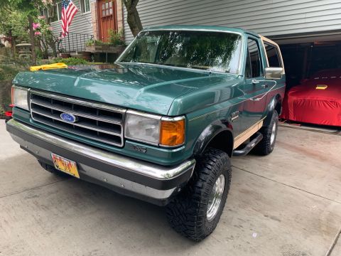
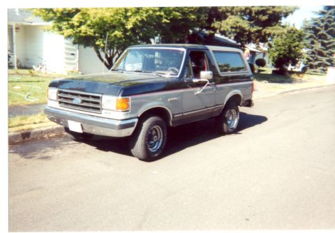
This document covers 1995, which may differ from this 1990 Ford Bronco.
Is this accurate? Sign in to help verify it.
Frequently asked questions
- What resistance should the 1995 Bronco transmission range (TR) sensor read in each gear?
- Testing between terminals 359 (GY/R) and 199 (LB/Y), a good switch reads 3770–4607 ohms in Park, 1304–1593 in Reverse, 660–807 in Neutral, 361–442 in Drive, 190–232 in Second (2), and 78–95 ohms in First (1).
- How do I test the backup lamp circuit on the TR sensor?
- Connect an ohmmeter to terminals 298 (P/O) and 140 (BK/PK). A good switch shows less than 5.0 ohms in Reverse and greater than 100K ohms in all other positions (Park, Neutral, Drive, Second, First).
- Which terminals test the starter relay circuit, and what readings are correct?
- Use the two 32 (R/LB) terminals. A good switch shows less than 5.0 ohms in Park and Neutral, and greater than 100K ohms in Reverse, Drive, Second (2), and First (1).
- How is the 4X4 Low-Neutral Sense circuit checked?
- Connect to terminals 463 (R/W) and 57 (BK). The circuit should be closed (continuity) only in Neutral and open in Park, Reverse, Drive, Second, and First.
- What are the wire colors on the E4OD TR sensor connector?
- The E4OD connector callouts are 32 (R/LB), 463 (R/W), 140 (BK/PK), 359 (GY/R), 298 (P/O), 199 (LB/Y), a second 32 (R/LB), and 57 (BK). The 4R70W connector adds circuit 33 (W/PK).
Comments
More from this build


No comments yet.