Ford EEC-IV Relay Box Location Diagram - Left Fender Apron (Bronco/F-Series)

Reference · 1987-1991 BroncoAll 95 service procedures
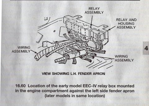












Illustration showing location of early-model EEC-IV relay and housing assembly mounted in the engine compartment against the left side fender apron with wiring assemblies.
Part of 1987-1991 Ford Bronco Service Procedures
This document is a single illustrated figure (numbered 16.60) from an automotive service manual showing the mounting location of the early model Ford EEC-IV relay box. The line drawing depicts the left-hand (L.H.) fender apron area of the engine compartment, with callout arrows identifying four items: the RELAY ASSEMBLY, the RELAY AND HOUSING ASSEMBLY, and two WIRING ASSEMBLY harnesses that route into the relay box. The caption states that the early model EEC-IV relay box is mounted in the engine compartment against the left side fender apron, and notes that later models have the relay box in the same location. A reader can use this figure to locate the EEC-IV relay/housing assembly on the driver's side inner fender when diagnosing engine management or relay problems, and to identify the associated wiring harness connections. The page carries a section tab number '4' in the margin, indicating it comes from chapter/section 4 of a repair manual. No fuse values, part numbers, wire colors, or specific model years are printed in this figure; it is purely a component location illustration.
Is this accurate? Sign in to help verify it.
Frequently asked questions
- Where is the EEC-IV relay box located?
- According to the figure, the early model EEC-IV relay box is mounted in the engine compartment against the left side fender apron, and later models have it in the same location.
- What components are identified in this diagram?
- The callouts identify the Relay Assembly, the Relay and Housing Assembly, and two Wiring Assemblies connecting to the relay box.
- Does the relay box location differ on later models?
- No. The caption states that later models have the relay box in the same location as early models, against the left side fender apron.
- What view does the illustration show?
- The drawing is labeled 'View showing L.H. fender apron,' meaning it depicts the left-hand fender apron area of the engine compartment.






No comments yet.