1995 Ford Bronco E4OD Transmission Wiring Diagram - Solenoids, PCM Pins (30-2)

Reference · 1987-1991 BroncoAll 175 wiring diagrams
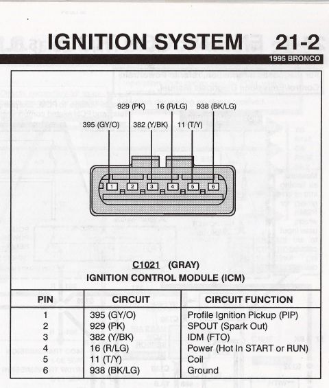
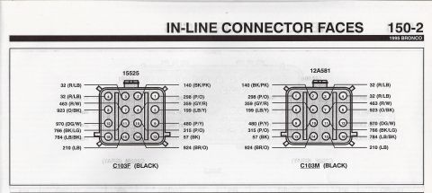
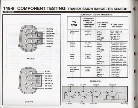
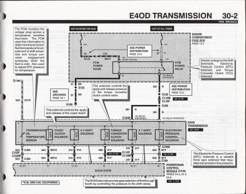
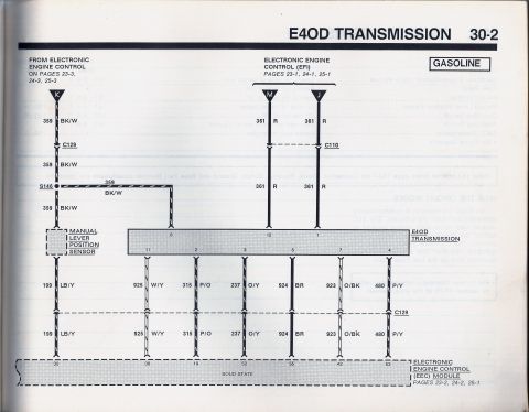
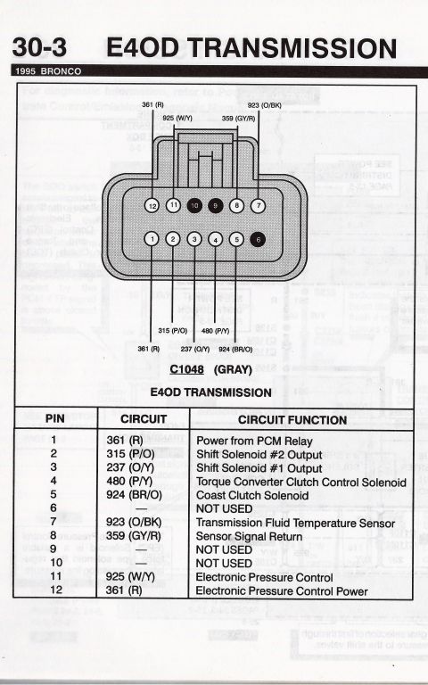
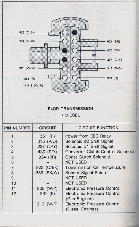









E4OD automatic transmission wiring schematic showing PCM control of the transmission oil temperature sensor, coast clutch, shift solenoids 1 and 2, TCC solenoid and Electronic Pressure Control (EPC) solenoid.
Part of 1987-1991 Ford Bronco Wiring Diagrams
This is page 30-2 of a 1995 Ford Bronco electrical/vacuum troubleshooting manual showing the complete wiring schematic for the E4OD automatic transmission control circuit. It shows power feeds from the engine compartment fuse box: a 20A fuse (hot in start or run) feeding circuit 16 R/LG through the PCM Power Diode via circuit 175 BK/Y, and a 20A fuse (hot at all times) feeding circuit 37 Y to the PCM Power Relay. The relay directs 12V on circuit 361 R (through splices S136, S169 and connectors C110M/C110F, C1048) to the transmission's shift solenoids, EPC solenoid, and TCC solenoid. Ground is via circuit 57 BK through S102 to G100. The transmission internal connector pinout shows the Transmission Oil Temperature Sensor (pins 8/7, circuits 359 GY/R and 923 O/BK), Coast Clutch Solenoid (pin 5, 924 BR/O), #2 Shift Solenoid (pin 2, 315 P/O), Torque Converter Clutch Solenoid (pin 4, 480 P/Y), #1 Shift Solenoid (pins 1/3, 237 O/Y), and Electronic Pressure Control Solenoid (pins 12/11, 925 W/Y), all terminating at PCM pins 42/49*, 55, 19/52*, 53, 52/51*, and 38 (asterisk = 5.0L and 5.8L California). Explanatory callouts describe how the PCM uses fluid temperature and how the solenoids operate.
This document covers 1995, which may differ from this 1990 Ford Bronco.
Is this accurate? Sign in to help verify it.
Frequently asked questions
- What wire color and circuit is the E4OD Electronic Pressure Control (EPC) solenoid on a 1995 Bronco?
- The EPC solenoid uses circuit 925 W/Y (white/yellow) on transmission connector pin 11, going to PCM pin 38, with 12V feed on pin 12 via circuit 361 R when the PCM Power Relay is energized.
- What fuses power the E4OD transmission circuit on a 1995 Bronco?
- Two 20A fuses in the engine compartment fuse box: one hot in start or run (circuit 16 R/LG through the PCM Power Diode via 175 BK/Y) and one hot at all times (circuit 37 Y to the PCM Power Relay).
- What are the PCM pin numbers for the E4OD shift solenoids?
- The #2 Shift Solenoid (circuit 315 P/O) goes to PCM pins 19 or 52*, and the #1 Shift Solenoid (circuit 237 O/Y) goes to PCM pins 52 or 51* (* = 5.0L and 5.8L California). The shift solenoids provide gear selection of first through fourth by controlling pressure to the shift valves.
- What does the E4OD transmission oil temperature sensor do?
- The PCM monitors the voltage drop across a temperature-sensitive thermistor to determine transmission fluid temperature, used to adjust shift schedules and torque converter engagement when the fluid is cold, and to adjust EPC pressure for temperature. It uses circuits 359 GY/R and 923 O/BK on pins 8 and 7.
- Where does the E4OD circuit get its ground?
- Circuit 57 BK runs from the PCM Power Diode/relay circuit through splice S102 to ground G100 (see Grounds, page 10-1).






No comments yet.