SuperMotors SuperMotors SUPERMOTORS Search — try “orange Bronco on 35s”
Home/ Registry/ Ford/ Bronco/ 1992-1996/ “Buckin Bronco”/ Photo supermotors.net/registry/media/937953

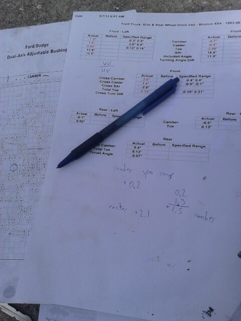
Wheel alignment printout sheet with handwritten camber and caste…

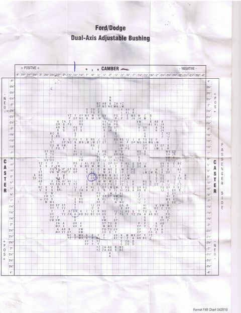
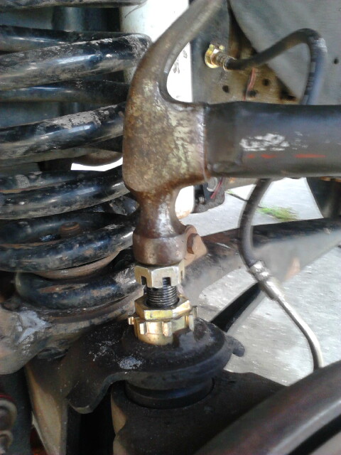
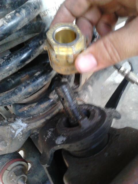
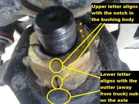
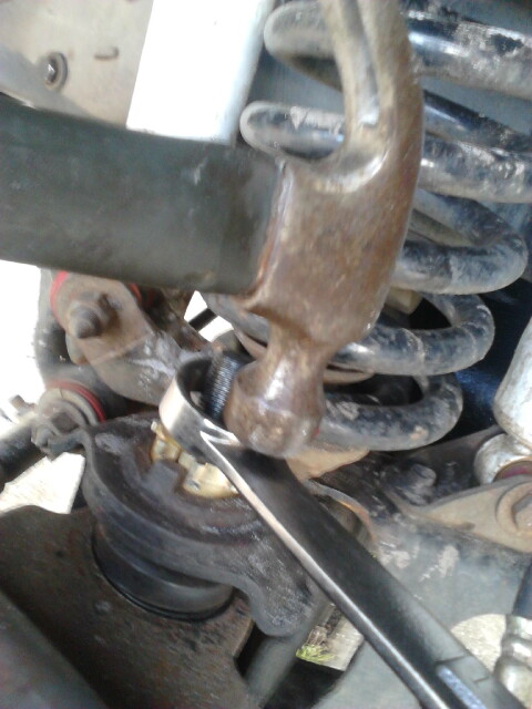
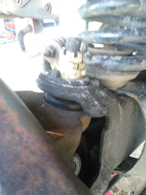
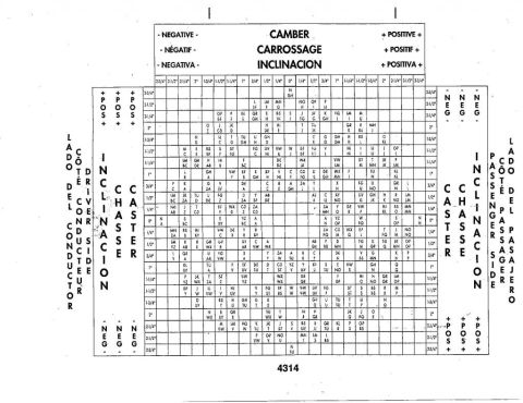
doing alittle quick math using the bushings chart and the before-alignment handout i found out where to set my bushings.

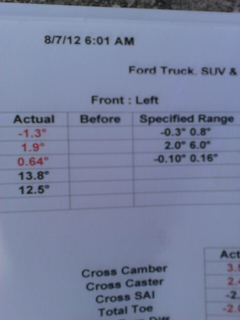
Since i had -1.3* camber and i want it to be about 0.2* i need a to add about 1.5* camber.

Since i had 1.9* caster and i want it to be about 4.0* i need to add about 2.1* caster which rounds to 2.0*

using the chart i need to bushing to be set at UV/UV or UV over UV. When 2 letters are together like this that means to set it between the 2 letters.

My other side axle is bent and has -4.7* camber and -0.6* caster. I would need a total of 4.9* camber and 4.6* caster to be perfect. since camber is more important and the bushing only can only add 3.2* i maxed the bushing to full camber.


For 2.75* to 0.75* chart, click this thumbnail


For 3.2* to 0* chart, click this thumbnail

Owner caption · Photo 62 of 386

Is this accurate? Sign in to help verify it.

Comments

No comments yet.

More from this build

Ford 5.8L California engine controls wiring diagram page 25-12, inertia fuel shutoff and fuel pump module Ford 5.8L California engine controls wiring diagram page 25-11, malfunction indicator lamp and HO2S Ford 5.8L California engine controls wiring diagram page 25-10, IAT sensor and heated oxygen sensor Ford 5.8L California engine controls wiring diagram page 25-9, EGR, ECT, TP and EGR valve position sensors Ford 5.8L California engine controls wiring diagram page 25-8, fuel injectors and idle air control circuits Ford 5.8L California engine controls wiring diagram page 25-7, PCM power relay and fuel pump circuits Vehicle Speed Sensor (VSS) wiring diagram, Bronco, page 64-2, rear axle sensor and PSOM circuits Vehicle Speed Sensor (VSS) wiring diagram, F-Series, page 64-1, rear axle sensor and PSOM circuits

More 1992-1996 Broncos