Home/
Registry/
Ford/
Ranchero/
1977-1979/
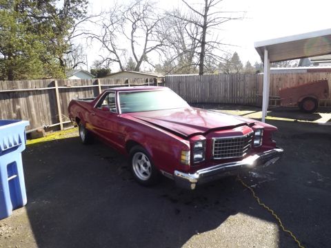
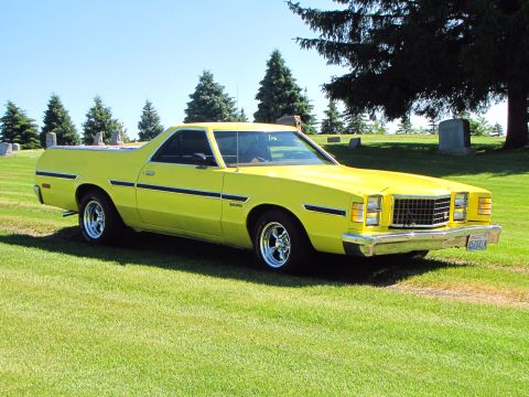
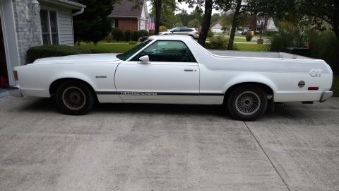
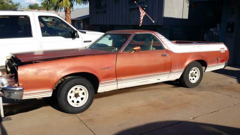
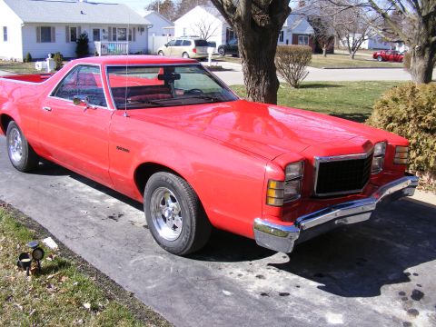
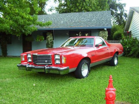
1979 Ford Ranchero/
Photo
supermotors.net/registry/media/974022
Ford Alternator Charging System Wiring Diagram - Indicator Light & Ammeter

Reference · 1977-1979 RancheroAll 4 wiring diagrams
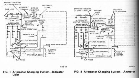
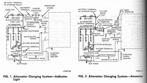
Wiring diagrams of the alternator charging system (indicator-light and ammeter versions) with color-coded wires and terminal labels.
Part of 1977-1979 Ford Ranchero Wiring Diagrams
This scanned page from a Ford service reference presents two schematic wiring diagrams of the alternator charging system. Figure 1 (drawing number J1210-1M) shows the charging system as used with a charge indicator (warning) light, including the battery, fuse link, black-orange fuse link, battery terminal of the starter relay, ignition switch accessory terminal, a 500-ohm resistor across the charge indicator light, and the alternator's internal components: diode rectifiers, stator windings, rotating field, and slip rings. Terminal designations (I, A+, S, F on the regulator side; BAT., STA., FLD. on the alternator) and wire color codes are labeled, including green-red stripe, yellow-white dot, white-black stripe, and orange/light blue wiring to the electric choke heater. Figure 2 (drawing number J1205-1L) shows the same charging system as equipped with an ammeter, noting a black/orange fuselink, a connection "used with shunt type ammeter," and one "not used with ammeter," plus the ignition terminal and switch, green-red stripe wire, and identical alternator internals. A reader can use this page to trace charging-circuit wiring, identify wire colors and terminal names, and understand the differences between indicator-light and ammeter-equipped charging systems on these Ford vehicles. Some text from the reverse page bleeds through but is largely unreadable.
Is this accurate? Sign in to help verify it.
Frequently asked questions
- What is the difference between the two alternator charging system diagrams shown?
- Figure 1 shows the alternator charging system with a charge indicator light (with a 500-ohm resistor across it), while Figure 2 shows the system used with an ammeter, including a connection used with a shunt-type ammeter and one marked 'not used with ammeter.'
- What resistor value is used with the charge indicator light?
- A 500-ohm resistor is shown wired across the charge indicator light in Figure 1.
- What wire colors are identified in the charging system?
- The diagrams label a green-red stripe wire, a yellow-white dot wire, a white-black stripe wire, an orange/light blue wire to the electric choke heater, and a black-orange (black/orange) fuse link.
- What terminals are labeled on the alternator?
- The alternator terminals shown are BAT. (alternator output terminal), STA. (stator terminal), and FLD. (field terminal); regulator-side terminals are labeled I, A+, S, and F.
- Where does the charging system connect to battery power?
- Both diagrams show the charging circuit connecting through a fuse link to the battery terminal of the starter relay.
No comments yet.