Home/
Registry/
Ford/
Bronco/
1978-1979/
1979 Ford Bronco/
Photo
supermotors.net/registry/media/1032660
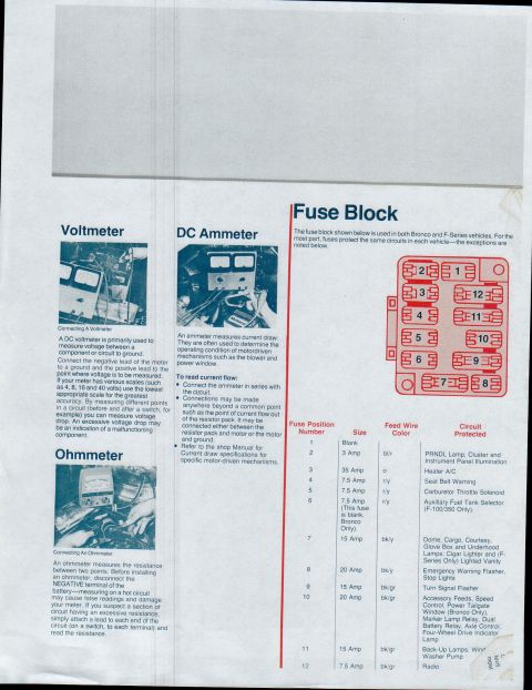
1979 Ford Bronco/F100-F350 Heater & A/C Electrical System Wiring Diagram

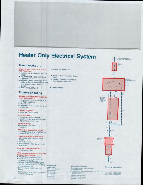
Heater/AC electrical wiring: blower motor, compressor clutch coil, de-icing switch, resistor pack through fuse 3; includes blower-speed continuity chart for wire 270 (bk/y) at connector C604.
This is page 41 of a Ford electrical reference guide (uploaded as part of a 1979 Bronco / F100-through-F350 set), covering the Heater and Air Conditioner Electrical System. It explains that the A/C-heater system has six basic electrical components: blower motor, compressor clutch coil, de-icing switch, blower speed switch, blower motor resistor, and the system OFF-ON/clutch switch. A detailed trouble-shooting flow addresses a blower motor that does not run in any position (check fuse 3, a 35-amp fuse hot when the ignition is in RUN), a blower working in only some speeds (checking wires 270 bk/y, 268 r/bk, and 269 bl/r at resistor connector C604), and a compressor clutch that does not engage. A full-page schematic shows the circuit from Fuse 3 through the A/C function control switch (Off, Vent, A/C, Hi/Lo, Heat, De-fog, Defrost), blower switch, resistor pack, de-icing switch, A/C clutch solenoid, and blower motor, with wire colors and connectors C604, C605, C613, C616, splices S603/S701, and ground G601. Tables list blower switch continuity connections by speed and component locations, plus a note that two types of blower switches with different terminal codes were used.
Is this accurate? Sign in to help verify it.
Frequently asked questions
- What fuse protects the heater/AC blower circuit and what is its rating?
- Fuse 3, rated 35 Amps; it is hot when the ignition switch is in RUN.
- What should I check first if the blower motor doesn't work in any switch position?
- Check fuse 3, verify the ignition switch is in the RUN position, and check the feed to fuse 3.
- What wire colors run to the blower motor resistor connector C604?
- Wire 270 (bk/y), wire 269 (bl/r), and wire 268 (r/bk).
- Where is the blower motor located?
- In the engine compartment, at the RH dash panel; the blower motor resistor is on the RH blower housing.
- What are the A/C function control switch positions?
- 1) Off, 2) Vent, 3) A/C, 4) Hi/Lo, 5) Heat, 6) De-fog, 7) Defrost.
- What does the note about two blower switch types mean?
- Two types of blower switches were used; terminal identification is on the connectors. One type uses codes like B-M1, the other uses numeric codes like (2)-(5).
Comments
More from this build

No comments yet.