Home/
Registry/
Ford/
Bronco/
1978-1979/
1979 Ford Bronco/
Photo
supermotors.net/registry/media/1032664
1979 Ford Bronco & F100-F350 Vacuum Distribution Diagram - Hose Routing

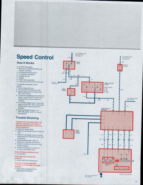
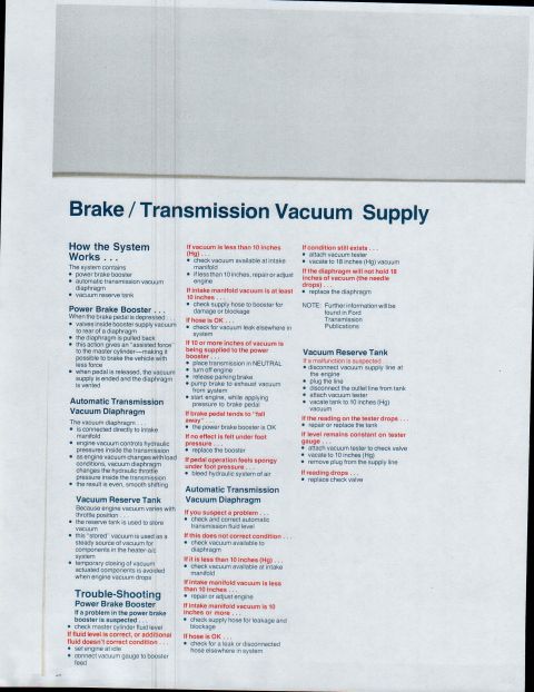
Vacuum distribution schematic routing engine vacuum to the power brake booster, A/C controls, automatic transmission diaphragm, speed control reservoir and EGR/EVAP.
This page (page 45 of a multi-page Ford truck reference set) is titled "Vacuum Distribution" and presents a schematic diagram of engine vacuum routing. The diagram shows a multi-port engine fitting (vacuum manifold/tree) mounted at the engine, with individual vacuum lines branching out to the various vacuum-operated systems. Labeled lines and destinations include: engine usage, speed control, air conditioning (with a line marked "TO A/C"), automatic transmission (routing down to an "AUTO. TRANS." component), and vacuum brakes. The vacuum brake line feeds the power brake booster, drawn as a round component. The speed control circuit routes through a connector to a speed control servo and also connects to a speed control vacuum reservoir, both illustrated as separate components on the right side of the diagram. A reader can learn how vacuum is distributed from the engine fitting to each accessory system, brakes, cruise (speed) control, A/C, and automatic transmission, and the general routing/connection order of hoses between those components. The page contains no part numbers, hose sizes, color codes, or year/model statements; it is purely a labeled routing schematic.
Is this accurate? Sign in to help verify it.
Frequently asked questions
- What systems receive vacuum from the engine fitting in this diagram?
- The diagram shows vacuum routed from the engine fitting to engine usage, speed control, air conditioning (A/C), the automatic transmission, and vacuum brakes (power brake booster).
- Where does the vacuum brake line go?
- The vacuum brakes line runs from the engine fitting to the power brake booster.
- What components are in the speed control vacuum circuit?
- The speed control line connects through a fitting to the speed control servo and to a speed control vacuum reservoir.
- Does the automatic transmission get a vacuum line?
- Yes, a line labeled AUTO. TRANS. runs from the engine fitting down to an automatic transmission component.
Comments
More from this build






No comments yet.