Home/
Registry/
Ford/
Bronco/
1978-1979/
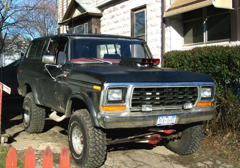
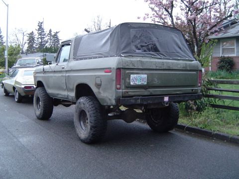
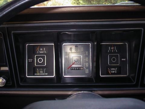
1979 Ford Bronco/
Photo
supermotors.net/registry/media/1032661
1978-79 Ford F100-F350 Bronco Heater/AC Vacuum System Diagram & Test Chart

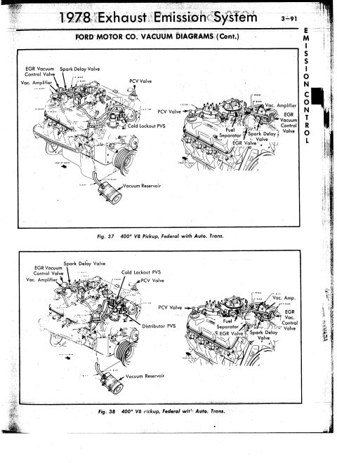
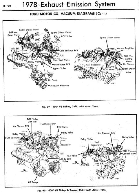
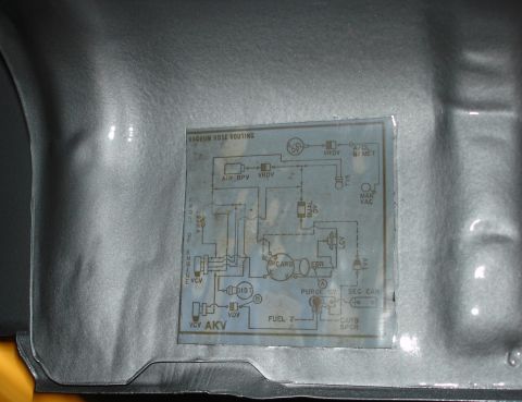
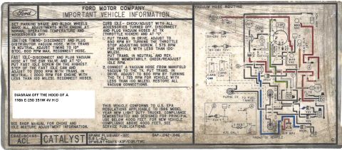
Reference · 1978-1979 BroncoAll 16 vacuum routing diagrams
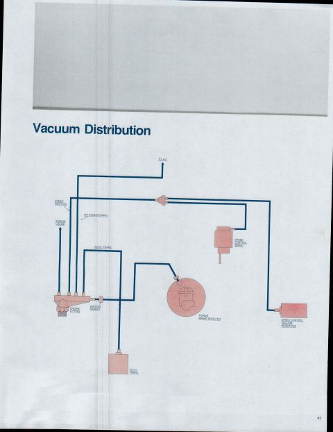
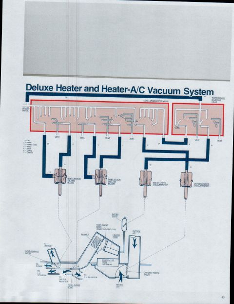
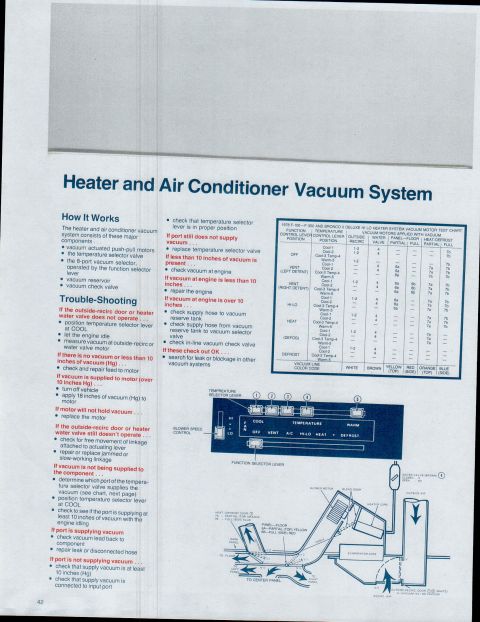
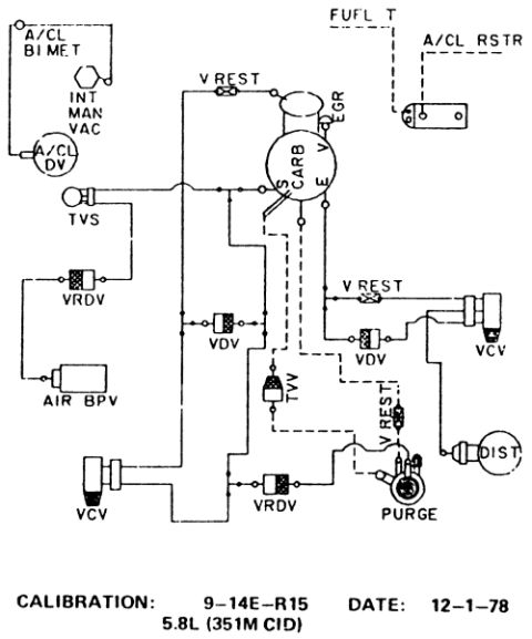
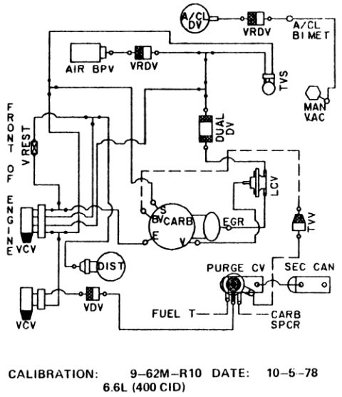
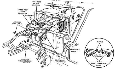
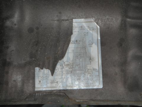

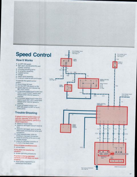
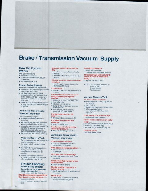
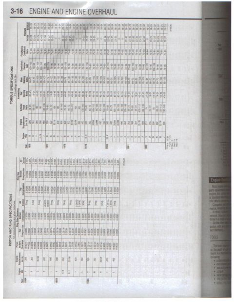
Heater/AC vacuum system operation plus a vacuum motor test chart listing applied vacuum (inches) per function/temperature lever position for outside, water, panel-floor, and heat-defrost motors.
Part of 1978-1979 Ford Bronco Vacuum Routing Diagrams
This page from a Ford factory reference booklet explains the heater and air conditioner vacuum system used on 1978 F-100 through F-350 trucks and the Bronco. It lists the system's major components (vacuum-actuated push-pull motors, temperature selector valve, 8-port vacuum selector operated by the function selector lever, vacuum reservoir, and vacuum check valve) and provides a step-by-step trouble-shooting procedure for cases where the outside-recirc door or heater water valve does not operate, including vacuum measurements (at least 10 inches Hg supply, 18 inches Hg applied to test a motor) and instructions to replace motors, valves, or repair hoses as required. A large 'Deluxe Hi Lo Heater System Vacuum Motor Test Chart' shows which vacuum motors (outside-recirc, water valve, panel-floor partial/full, heat-defrost partial/full) are applied with vacuum for every combination of function lever position (OFF, VENT left/right detent, HI-LO, HEAT, DEFOG, DEFROST) and temperature lever position (Cool-1 through Warm-5), with a vacuum line color code (white, brown, yellow, red, orange, blue). Diagrams show the dash control panel with its levers and an airflow/vacuum-motor schematic of the blower motor, blend door, heater core, evaporator core, water valve, and outside-recirc door.
Is this accurate? Sign in to help verify it.
Frequently asked questions
- How much vacuum should be supplied to the heater/AC vacuum motors at idle?
- The document says supply vacuum should be at least 10 inches of vacuum (Hg) with the engine idling; less than 10 inches indicates a supply or engine problem.
- How do I test a vacuum motor for the outside-recirc door or heater water valve?
- Turn off the vehicle and apply 18 inches of vacuum (Hg) to the motor. If the motor will not hold vacuum, replace the motor.
- What are the vacuum line colors in the Hi-Lo heater system?
- White (outside-recirc), brown (water valve), yellow-top and red-side (panel-floor partial/full), orange-top and blue-side (heat-defrost partial/full).
- What are the major components of the heater and A/C vacuum system?
- Vacuum actuated push-pull motors, the temperature selector valve, the 8-port vacuum selector operated by the function selector lever, a vacuum reservoir, and a vacuum check valve.
- What should I check if vacuum at the engine is over 10 inches but the system still fails?
- Check the supply hose to the vacuum reserve tank, the hose from the reserve tank to the vacuum selector valve, and the in-line vacuum check valve; if those are OK, search for a leak or blockage in other vacuum systems.
No comments yet.