Home/
Registry/
Ford/
Bronco/
1978-1979/
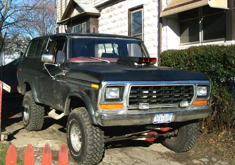
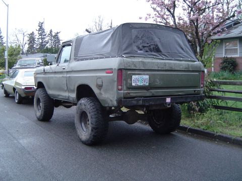
1979 Ford Bronco/
Photo
supermotors.net/registry/media/1032662
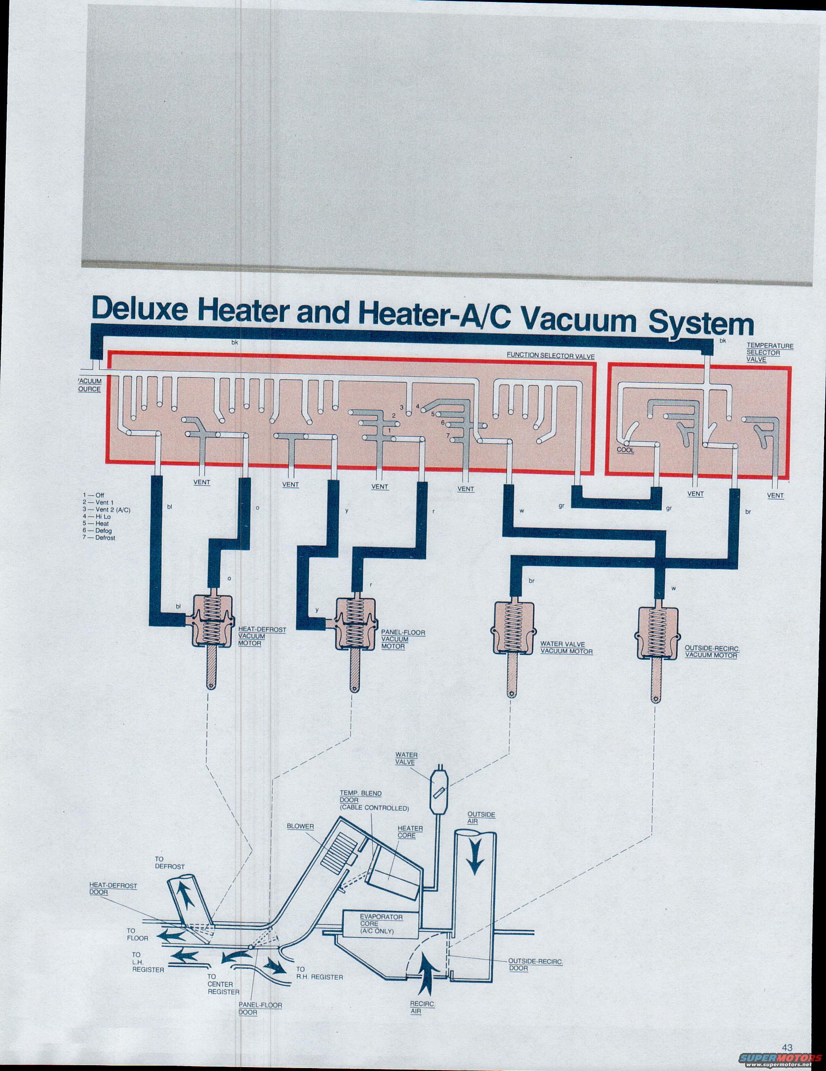
1979 Ford Bronco/F100-F350 Deluxe Heater & Heater-A/C Vacuum System Diagram
Reference · 1978-1979 BroncoAll 16 vacuum routing diagrams
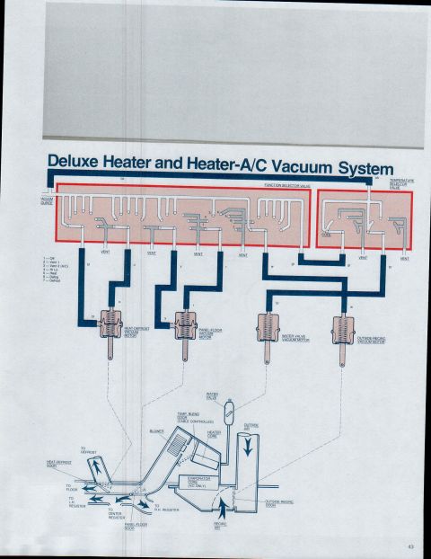

Vacuum routing schematic for temperature selector valve and a-port selector feeding water valve, outside-recirc, temp blend door, and panel/floor/defrost vacuum motors with color-coded hose paths.
Part of 1978-1979 Ford Bronco Vacuum Routing Diagrams
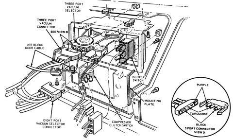
This document is page 43 of a Ford factory reference set (filed as '1979 Bronco F100 through F350') showing the 'Deluxe Heater and Heater-A/C Vacuum System' vacuum routing diagram. It illustrates how engine vacuum from the vacuum source (black hose) routes through the function selector valve and the temperature selector valve to four vacuum motors: the heat-defrost vacuum motor, panel-floor vacuum motor, water valve vacuum motor, and outside-recirc. vacuum motor. Hose color codes are identified by abbreviations (bk, bl, o, y, r, w, gr, br). A legend lists the seven selector positions: 1: Off, 2, Vent 1, 3, Vent 2 (A/C), 4, Hi Lo, 5, Heat, 6, Defog, 7, Defrost. Several valve ports are labeled VENT, and the temperature selector valve includes a COOL port. A lower cutaway drawing of the HVAC plenum shows air flow through the blower, evaporator core (A/C only), heater core, cable-controlled temp blend door, water valve, heat-defrost door, panel-floor door, and outside-recirc. door, with air routed to the defrost, floor, and left, center, and right registers, plus outside air and recirculated air inlets. Useful for diagnosing vacuum-operated HVAC door problems and hose routing on these trucks.
Is this accurate? Sign in to help verify it.
Frequently asked questions
- What vacuum motors are used in the Deluxe Heater and Heater-A/C system?
- Four vacuum motors are shown: the heat-defrost vacuum motor, the panel-floor vacuum motor, the water valve vacuum motor, and the outside-recirc. vacuum motor.
- What are the function selector positions on this system?
- The legend lists seven positions: 1: Off, 2, Vent 1, 3, Vent 2 (A/C), 4, Hi Lo, 5, Heat, 6, Defog, 7, Defrost.
- What hose colors connect to each vacuum motor?
- The heat-defrost vacuum motor uses blue (bl) and orange (o) hoses, the panel-floor vacuum motor uses yellow (y) and red (r), the water valve vacuum motor uses brown (br), and the outside-recirc. vacuum motor uses white (w). The vacuum source and temperature selector valve feed are black (bk).
- Is the temperature blend door vacuum operated?
- No: the diagram labels the temp. blend door as cable controlled.
- Which components does air pass through in the HVAC housing?
- Air enters as outside or recirc. air through the outside-recirc. door, passes the blower, evaporator core (A/C only), and heater core, then is directed by the heat-defrost and panel-floor doors to the defrost outlet, floor, and left, center, and right registers.
No comments yet.