Ford E4OD Transmission PCM Wiring Diagram - MAF, TP, ECT, TCS & BOO Switch (T3)
Reference · 1987-1991 F-250All 32 wiring diagrams

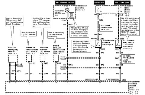
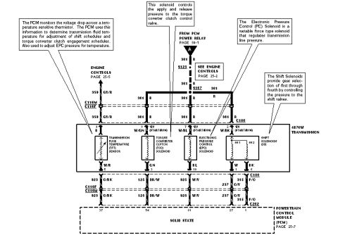
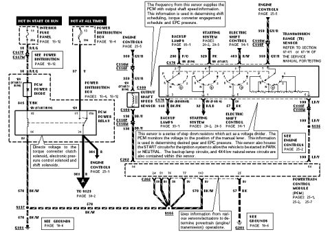
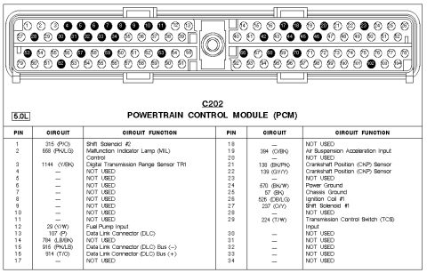

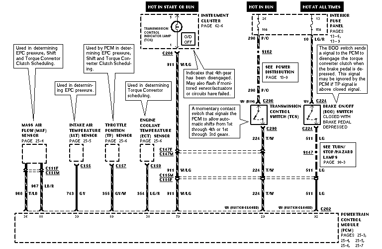
Wiring diagram showing MAF, IAT, TP and ECT sensor circuits to the PCM with transmission control switch and color-coded wires.
Part of 1987-1991 Ford F-250 Wiring Diagrams
This is a Ford powertrain/transmission control wiring diagram (page T3 of a multi-page set) showing sensor and switch inputs to the Powertrain Control Module (PCM). It covers the Mass Air Flow (MAF) sensor, Intake Air Temperature (IAT) sensor, Throttle Position (TP) sensor, and Engine Coolant Temperature (ECT) sensor, along with the Transmission Control Indicator Lamp (TCIL/O-D OFF lamp in the instrument cluster), the Transmission Control Switch (TCS), and the Brake On/Off (BOO) switch. Wire circuit numbers and colors are given: 968 T/LB and 967 LB/R (MAF), 743 GY (IAT), 355 GY/W (TP), 354 LG/R (ECT), 911 W/LG (TCIL), 224 T/W (TCS), 511 LG and 10 LG/R (BOO), 298 P/O (hot in run feed). Connectors identified include C286, C290, C224, C202, C111F/C111M, C155, C157, C153, C115M/C115F, and C147F/C147M, plus splices S162 and S147. PCM pin numbers shown are 36, 88, 33, 89, 38, 79, 29, and 32. Explanatory callouts describe each input's role in EPC pressure, shift, and torque converter clutch scheduling, that the TCIL flashes for monitored circuit failures, and that the BOO switch signal disengages the torque converter clutch when braking. Cross-references point to pages 25-3 through 25-7, 13-6, 13-9, 62-6, and 90-3.
Is this accurate? Sign in to help verify it.
Frequently asked questions
- What does the Transmission Control Indicator Lamp (TCIL) indicate?
- It indicates that 4th gear has been disengaged, and it may also flash if monitored sensors/actuators or circuits have failed. It is located in the instrument cluster (O/D OFF lamp) and connects to PCM pin 79 via circuit 911 W/LG through connector C286 and C147F/C147M.
- What does the Transmission Control Switch (TCS) do?
- It is a momentary contact switch that signals the PCM to allow automatic shifts from 1st through 4th or 1st through 3rd gears. It is fed by circuit 298 P/O (hot in run) and connects to PCM pin 29 on circuit 224 T/W through connector C290.
- What is the function of the Brake On/Off (BOO) switch in this diagram?
- The BOO switch, closed with the brake pedal depressed, sends a signal to the PCM to disengage the torque converter clutch when braking. The signal may be ignored by the PCM if the TP signal is above closed signal. It is fed hot at all times through fuse 13 (15A) on circuit 10 LG/R and connects to PCM pin 32 on circuit 511 LG.
- Which sensors are used to determine EPC pressure?
- The Mass Air Flow (MAF) sensor, Intake Air Temperature (IAT) sensor, and Throttle Position (TP) sensor are all used in determining EPC pressure; the MAF and TP are also used for shift and torque converter clutch scheduling, while the ECT sensor is used for torque converter scheduling.
- What wire colors and PCM pins are used for the sensor inputs?
- MAF: 968 T/LB and 967 LB/R to PCM pins 36 and 88; IAT: 743 GY to pin 33; TP: 355 GY/W to pin 89; ECT: 354 LG/R to pin 38.






No comments yet.