Ford F-Series PCM Wiring Diagram - WOT A/C Relay, EVAP Purge & Coil Outputs (E2)
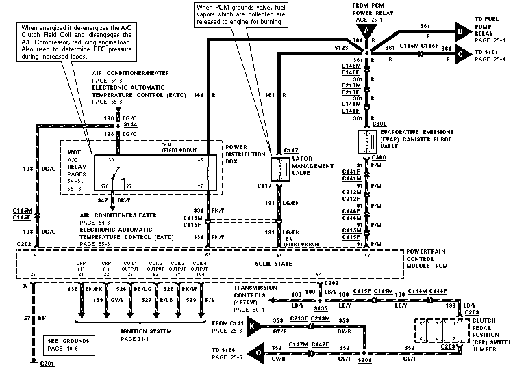
Wiring diagram of A/C clutch relay, EVAP canister purge valve, vapor management and ignition circuits to the PCM with color codes.
This is one page (E2) of a multi-page Ford factory-style wiring diagram set covering engine/powertrain control circuits. It shows the Powertrain Control Module (PCM) and its related circuits: the PCM power relay feed (circuit 361 R) branching through splice S123 to the fuel pump relay, S101, the WOT A/C relay inside the Power Distribution Box, the Vapor Management Valve (C117), and the EVAP canister purge valve. Callout notes explain that the WOT A/C relay de-energizes the A/C clutch field coil to reduce engine load and is used to determine EPC pressure, and that the PCM grounds the vapor management valve to release collected fuel vapors to the engine. The lower portion shows PCM outputs to the ignition system (CKP+, CKP-, and Coil 1-4 outputs, circuits 138, 526-529), the transmission controls (4R70W) circuit 199 LB/Y, the clutch pedal position (CPP) switch jumper at C209, and circuit 359 GV/R routing between C141, S166, and ground splices. Numerous connector (C115, C141, C146, C147, C202, C209, C212, C213, C300), splice (S123, S135, S144, S201), and ground (G201) identifiers are labeled with wire colors, along with cross-references to EVTM pages 10-6, 21-1, 25-1, 25-3, 25-4, 30-1, 54-3, and 55-3.
Is this accurate? Sign in to help verify it.
Frequently asked questions
- What does the WOT A/C relay do according to this diagram?
- When energized, it de-energizes the A/C Clutch Field Coil and disengages the A/C Compressor, reducing engine load. It is also used to determine EPC pressure during increased loads.
- How does the Vapor Management Valve work in this circuit?
- When the PCM grounds the valve, fuel vapors which are collected are released to the engine for burning. The valve (at connector C117) is fed by circuit 361 R and returns on circuit 191 LG/BK to the PCM.
- What wire circuit feeds the PCM power relay branch on this page?
- Circuit 361 (Red) from the PCM Power Relay (page 25-1) splits at splice S123 to the fuel pump relay, S101, the WOT A/C relay, the Vapor Management Valve, and the EVAP canister purge valve.
- Which PCM pins drive the ignition coils?
- The diagram shows CKP (+), CKP (-), and Coil 1-4 outputs at PCM pins 25, 21, 26, 22, 78, and 104, on circuits including 138 BK/PK, 526 DG, 527, 528 PK/W, and 529, going to the Ignition System (page 21-1).
- What transmission is referenced on this diagram?
- Transmission Controls for the 4R70W are referenced on page 30-1, connected via circuit 199 LB/Y through connectors C202, C115, and C209 (Clutch Pedal Position switch jumper).
Comments
More from this build

No comments yet.