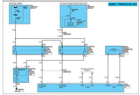
Hyundai Genesis Coupe 2.0L MAPS/BPS Wiring Diagram & ECM CHG-K Pinout

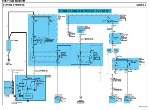
BPS (CHG25-2) sensor circuit diagram and connector pinout to ECM CHG-K: sensor power +5V pin 10, MAPS signal pin 11, sensor ground pin 43; describes ECTS coolant temp NTC thermistor operation.
This service-manual page covers the Fuel System section for a Hyundai Genesis Coupe (per uploader, 2.0L pre-throttle-body MAP sensor). It contains a circuit diagram showing the BPS (Boost Pressure Sensor / MAPS, connector CHG25-2) wired to the ECM connector CHG-K: BPS terminal 2 to ECM pin 43 (Sensor Power +5V), terminal 4 to ECM pin 11 (Sensor Ground), and terminal 1 to ECM pin 10 (MAPS Signal). A Connection Information table lists each terminal's ECM pin and function; terminal 3 is unused. Harness connector views show the 4-pin BPS connector (pins numbered 4-3-2-1) and the full 94-pin (plus 6-pin) CHG-K ECM connector pinout, with pins 43, 11, and 10 highlighted. An Inspection procedure instructs connecting a GDS scan tool to the Data Link Connector (DLC) and measuring MAPS output voltage at idle and IG ON, referring to the Specification section. The page also includes a Description of the Engine Coolant Temperature Sensor (ECTS), explaining its thermistor operation, series resistor with the ECM's 5V reference, and how the ECM uses coolant temperature to increase fuel injection duration and adjust ignition timing during cold operation.
Is this accurate? Sign in to help verify it.
Frequently asked questions
- Which ECM pins connect to the MAP/boost pressure sensor (BPS) on this Genesis Coupe?
- BPS terminal 2 connects to ECM CHG-K pin 43 (Sensor Power +5V), terminal 4 to pin 11 (Sensor Ground), and terminal 1 to pin 10 (MAPS Signal). Terminal 3 is not connected.
- What is the BPS connector designation?
- The BPS uses connector CHG25-2, a 4-pin connector, while the ECM connector is CHG-K.
- How do you inspect the MAPS according to this document?
- Connect a GDS scan tool on the Data Link Connector (DLC) and measure the output voltage of the MAPS at idle and with IG ON, comparing to the value in the 'Specification' section.
- How does the ECTS work according to this page?
- The Engine Coolant Temperature Sensor is a thermistor in the cylinder head coolant passage. Its resistance decreases as temperature increases. It is in series with a resistor on the ECM's 5V reference, so the output voltage changes with coolant temperature.
- What does the ECM do with coolant temperature data during cold operation?
- During cold engine operation the ECM increases fuel injection duration and controls ignition timing using coolant temperature information to avoid engine stalling and improve drivability.
Comments
More from this build

No comments yet.