Home/
Registry/
Hyundai/
Genesis Coupe/
2010-2016/
“Coupe”/
Photo
supermotors.net/registry/media/1077342
Hyundai Genesis Coupe 2.0L MAPS & IATS Sensor Wiring Diagram - ECM CHG-K Pinout
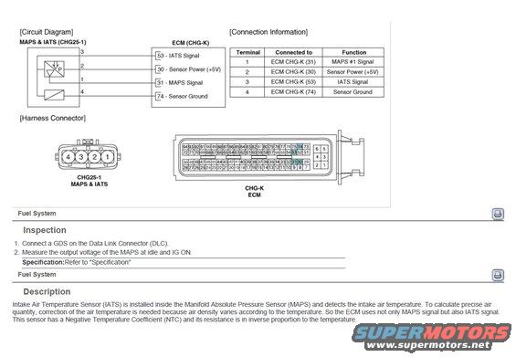
MAPS & IATS (CHG25-1) sensor circuit diagram and connector pinout: IATS signal to ECM pin 31, sensor power +5V pin 30, MAPS signal pin 31, sensor ground pin 74; NTC intake air temp sensor.
Part of 2010-2016 Hyundai Genesis Coupe Wiring Diagrams
This service manual page covers the Manifold Absolute Pressure Sensor (MAPS) with integrated Intake Air Temperature Sensor (IATS), connector CHG25-1, and its wiring to the ECM connector CHG-K. The circuit diagram shows the four sensor terminals: terminal 1 (MAPS #1 Signal) to ECM pin 31, terminal 2 (Sensor Power +5V) to ECM pin 30, terminal 3 (IATS Signal) to ECM pin 53, and terminal 4 (Sensor Ground) to ECM pin 74. A connection information table repeats these terminal assignments. Harness connector views show the 4-pin MAPS & IATS connector (pins 4-3-2-1) and the full 94-pin ECM connector pin layout with pins 30, 31, 53, and 74 highlighted. The Inspection procedure instructs connecting a GDS scan tool to the Data Link Connector (DLC) and measuring MAPS output voltage at idle and with ignition ON, referring to the "Specification" section for values. The Description section explains that the IATS is built into the MAPS, that the ECM uses both signals to correct calculated air quantity for air-density changes with temperature, and that the IATS is an NTC thermistor whose resistance decreases as temperature increases. Filed under the Fuel System section of the manual.
Is this accurate? Sign in to help verify it.
Frequently asked questions
- Which ECM pin does the MAPS signal connect to?
- MAPS #1 Signal on sensor terminal 1 connects to ECM CHG-K pin 31.
- What are the pin functions of the MAPS/IATS connector CHG25-1?
- Terminal 1: MAPS #1 Signal (ECM pin 31); Terminal 2: Sensor Power +5V (ECM pin 30); Terminal 3: IATS Signal (ECM pin 53); Terminal 4: Sensor Ground (ECM pin 74).
- How do you inspect the MAPS according to this document?
- Connect a GDS to the Data Link Connector (DLC) and measure the output voltage of the MAPS at idle and with IG ON, comparing to the 'Specification' section.
- Where is the IATS located?
- The Intake Air Temperature Sensor (IATS) is installed inside the Manifold Absolute Pressure Sensor (MAPS).
- What type of sensor element is the IATS?
- It has a Negative Temperature Coefficient (NTC), its resistance is in inverse proportion to temperature.
Comments
More from this build









No comments yet.