Home/
Registry/
Hyundai/
Genesis Coupe/
2010-2016/
“Coupe”/
Photo
supermotors.net/registry/media/1077384
Hyundai Genesis Coupe 2.0T G4KF Engine Control Wiring Diagram SD313-7 MAP/Boost

Reference · 2010-2016 Genesis CoupeAll 79 wiring diagrams
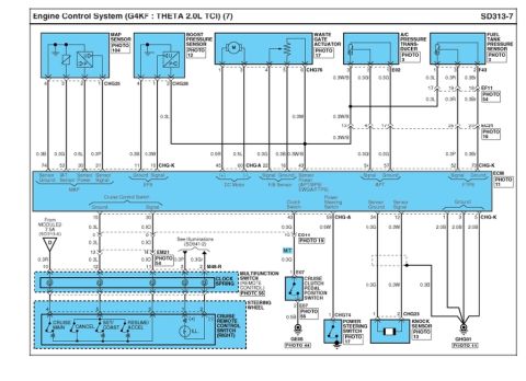








Engine control system wiring diagram for a Theta 2.0L turbo showing MAP, boost, knock and pressure sensors plus cruise and wastegate circuits.
Part of 2010-2016 Hyundai Genesis Coupe Wiring Diagrams
This is page SD313-7 of a Hyundai factory wiring diagram covering the Engine Control System for the G4KF THETA 2.0L TCI (turbocharged) engine, sheet 7 of the series. It shows ECM (PHOTO 11) wiring for the MAP sensor (connector CHG25), boost pressure sensor (CHG26), waste gate actuator DC motor and feedback sensor (CHG76), A/C pressure transducer (E02), and fuel tank pressure sensor (F43), including ECM pin numbers (e.g., 74/53/30/31 for MAP; 45/60/22/16/43 for the waste gate; 54/57 for APT; 52/73 for FTPS), wire colors/gauges (0.3B, 0.3G, 0.5L, 0.3P, 0.3W/B, 2.0B, etc.), and intermediate connectors EF11, EC21, EM21, and EC11 with photo references. The lower portion diagrams the cruise control system: power from MODULE2 7.5A fuse (SD313-6), the clock spring / multifunction switch (remote control), and the steering-wheel-mounted cruise remote control switch (CRUISE MAIN, CANCEL, SET/COAST, RESUME/ACCEL with illumination), plus the cruise clutch pedal position switch (E07, manual transmission), power steering switch (CHG74), knock sensor (CHG23), and ECM grounds at GHG01. A reader can identify ECM terminal assignments, wire colors, connector names, and ground points for diagnosing these sensors and the cruise control circuit.
Is this accurate? Sign in to help verify it.
Frequently asked questions
- What ECM pins does the MAP sensor connect to on the G4KF 2.0L TCI engine?
- The MAP sensor (connector CHG25) connects to ECM pins 74 (Sensor Ground, 0.3B), 53 (IAT Sensor, 0.3G), 30 (Sensor Power, 0.5L), and 31 (Sensor Signal, 0.3P).
- Which connector is used for the boost pressure sensor and what are its wire colors?
- The boost pressure sensor uses connector CHG26 (pins 4, 1, 2) with wires 0.3B, 0.3W, and 0.3L, going to ECM pins 11 (Ground) and 10 (Signal) in the EPS group.
- How is the waste gate actuator wired to the ECM?
- The waste gate actuator (connector CHG76, PHOTO 17) uses ECM pins 45 and 60 for the DC motor (+/-, 0.5R and 0.5L), pin 22 for the F/B sensor signal (0.3G), pin 16 for ground (0.3B), and pin 43 for sensor power (0.3W/B, shared with APT/BPS/EWGA/FTPS).
- What does the cruise remote control switch on the steering wheel include?
- The cruise remote control switch (right side of the steering wheel) includes CRUISE MAIN, CANCEL, SET/COAST, and RESUME/ACCEL positions plus an illumination lamp, wired through the clock spring / multifunction switch (remote control).
- Where does the knock sensor connect on this diagram?
- The knock sensor (connector CHG23, PHOTO 13) connects to ECM pin 34 (Sensor Ground, 0.3G) and pin 12 (Sensor Signal, 0.3W).

No comments yet.