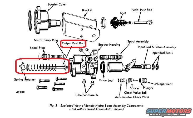
Bendix Hydro-Boost Brake Booster Exploded Parts Diagram - Component Names
Reference · 1966-1977 BroncoAll 140 exploded parts diagrams

Exploded view of a Bendix Hydro-Boost brake booster assembly with labeled components and the output push rod highlighted.
Part of 1966-1977 Ford Bronco Exploded Parts Diagrams
This document is an exploded parts diagram (labeled Fig. 3) showing the components of a Bendix Hydro-Boost brake booster assembly, specifically a unit with an external accumulator. The illustration identifies each part of the hydraulic brake booster in disassembled order, including the booster cover, bracket, boot, pedal push rod, spiral snap ring, output push rod (highlighted with a red circle in this scan, along with the return spring and spring retainer), booster housing, spool assembly, spool plug, input rod & piston assembly, input rod seals, spring retainer, piston seal, tube seat inserts, spacer, plunger, plunger seat, check valve ball, and accumulator check valve. A figure code '4CH01' appears in the lower left. The red highlighting suggests the uploader was pointing out the output push rod and its return spring/retainer assembly, likely relevant to a repair or parts identification question. No year, model, engine, part numbers, or torque specifications are printed on the diagram itself. A reader can learn the names, relative positions, and assembly order of all major internal and external components of the Bendix Hydro-Boost unit, which is useful when disassembling, rebuilding, or ordering replacement parts for this hydraulically assisted power brake booster.
Is this accurate? Sign in to help verify it.
Frequently asked questions
- What does this diagram show?
- It is Fig. 3, an exploded view of Bendix Hydro-Boost brake booster assembly components, shown as a unit with an external accumulator.
- What parts are highlighted in the diagram?
- A red circle highlights the Output Push Rod label and the output push rod with its return spring and spring retainer.
- What components make up the Hydro-Boost assembly in this diagram?
- Booster cover, bracket, boot, pedal push rod, spiral snap ring, output push rod, booster housing, spool plug, spool assembly, input rod & piston assembly, input rod seals, spring retainer, piston seal, tube seat inserts, spacer, plunger, plunger seat, check valve ball, and accumulator check valve.
- Does this unit have an internal or external accumulator?
- The caption states the unit shown has an external accumulator, and an accumulator check valve with check valve ball, spacer, plunger, and plunger seat are labeled.

No comments yet.