Home/
Registry/
Ford/
Bronco/
1966-1977/
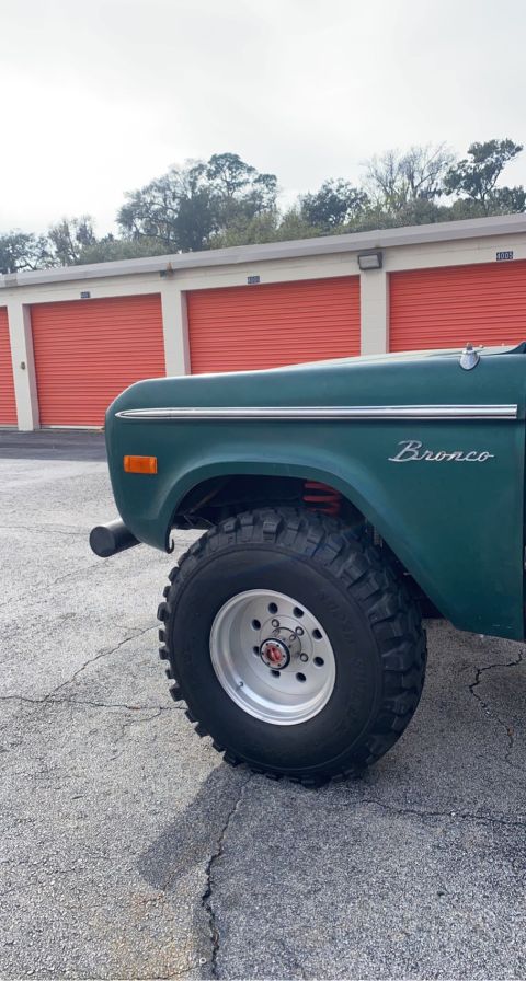
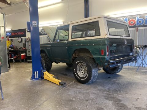
1976 Ford Bronco/
Photo
supermotors.net/registry/media/1166864
Ford Duraspark Ignition Module Wiring Diagram - Blue Connector Conversion

Wiring diagram showing how to wire a Duraspark ignition module and coil to a starter relay with color-coded wires and start/run current flow.
This document is a hand-annotated wiring diagram, credited to MustangSteve (http://www.mustangsteve.com), showing how to wire a Ford Duraspark ignition module (the version with the blue connector) to a 12-volt high-performance coil, starter relay, and distributor module. Gray lines represent existing vehicle wires, while red and green arrows indicate current flow in the START and RUN ignition positions respectively. Instructions include disconnecting the brown wire from the starter relay and the red/green wire from the coil, and disconnecting the pink (resistance) wire; a red wire is instead tapped at a plug approximately 4 inches from the ignition switch to provide 12 volts. The starter relay's "S" and "I" terminals are shown, with the brown wire routing and a note that 12 volts is present in "start" only. Wire colors from the Duraspark module to the distributor and coil are labeled: red, green, orange, purple, black, white, and red/blue. The diagram shows the firewall location and how the module connects between the ignition switch feed, the coil positive terminal, and the distributor pickup. A reader can learn the complete hookup for converting to Duraspark ignition, including which factory wires to disconnect and which module wires go where.
Is this accurate? Sign in to help verify it.
Frequently asked questions
- Which factory wires need to be disconnected for this Duraspark conversion?
- Disconnect the brown wire from the starter relay, the red/green wire from the coil, and the pink wire (near the firewall).
- Where does the 12-volt feed for the Duraspark module come from?
- A red wire is connected to a plug approximately 4 inches from the ignition switch, providing 12 volts.
- What do the gray lines and colored arrows on the diagram mean?
- Gray lines are existing wires. Red arrows show current flow in START and green arrows show current flow in RUN.
- What wire colors run between the Duraspark module and the distributor/coil?
- The diagram labels red, green, orange, purple, black, white, and red/blue wires connecting the Duraspark module, distributor module, and coil.
- Which starter relay terminal supplies 12 volts only in start?
- The diagram notes '12 volts in "start" only' from the starter relay, whose "S" and "I" terminals are shown, with the white wire path carrying it.
Comments
More from this build

No comments yet.