VDO Electronic Speedometer Wiring Diagram - Inductive Sender & ECU Signal Pinout
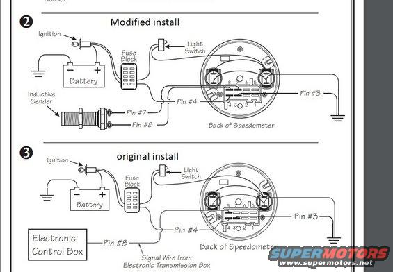
Wiring diagram comparing modified and original speedometer installs with battery, fuse block, sender and labeled pin connections.
This document is a two-part wiring diagram (labeled steps 2 and 3) showing how to wire an electronic speedometer, apparently a VDO-style gauge based on the uploader's filename. Diagram 2, titled 'Modified install', shows the speedometer wired to a battery, ignition switch (with ground), fuse block, and light switch, with an inductive sender connected to Pin #7 and Pin #8 on the back of the speedometer. Pin #4 receives switched power via the fuse block and Pin #3 goes to ground. Diagram 3, titled 'original install', shows the same battery/ignition/fuse block/light switch arrangement, but instead of an inductive sender, Pin #8 receives a signal wire from an 'Electronic Control Box' (noted as the signal wire from the electronic transmission box). Both diagrams depict the back of the speedometer with an 8-pin connector numbered 8-7-6-5 across the top row and 4-3-2-1 across the bottom row. A reader can learn which speedometer pins carry speed signal (Pins #7/#8 for inductive sender, Pin #8 for ECU signal), power (Pin #4), and ground (Pin #3), and how the fuse block and light switch integrate into the circuit.
Is this accurate? Sign in to help verify it.
Frequently asked questions
- Which pins does the inductive sender connect to on the speedometer?
- In the 'Modified install' diagram, the inductive sender connects to Pin #7 and Pin #8 on the back of the speedometer.
- Where does the speed signal come from in the original install?
- In the 'original install' diagram, Pin #8 receives a signal wire from the Electronic Control Box, identified as the signal wire from the electronic transmission box.
- Which pin is the ground on this speedometer?
- Pin #3 is shown going to ground in both diagrams.
- How is power supplied to the speedometer?
- Power runs from the battery through the ignition switch and a fuse block, then to Pin #4 on the speedometer; a light switch also feeds the gauge for illumination.
- How are the connector pins arranged on the back of the speedometer?
- The 8-pin connector is drawn with pins 8, 7, 6, 5 across the top row and pins 4, 3, 2, 1 across the bottom row.
Comments
More from this build

No comments yet.