Ford 5.0L Heater Hose Restrictor Location & Routing Diagram (TB-3206-A)
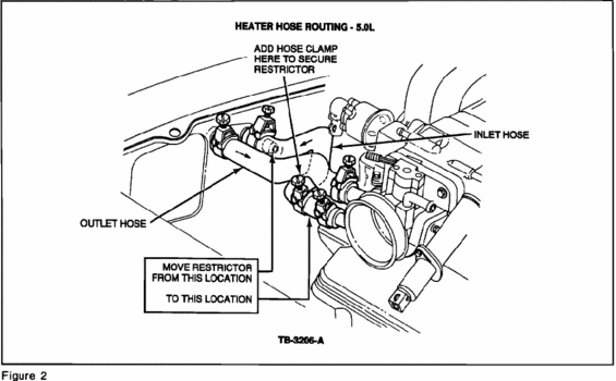
Heater hose routing schematic for a 5.0L engine showing inlet and outlet hoses and restrictor placement.
This document is a technical illustration (labeled Figure 2, drawing number TB-3206-A) showing heater hose routing for a 5.0L engine. The line drawing depicts the engine bay area around the throttle body and upper intake, with the heater inlet and outlet hoses identified by callouts. The central instruction concerns relocating a heater hose restrictor: an arrow-and-box callout directs the reader to "MOVE RESTRICTOR FROM THIS LOCATION TO THIS LOCATION," indicating the restrictor should be moved from a position in the outlet hose near the firewall/cowl area to a position closer to the throttle body in the hose run. An additional callout instructs to "ADD HOSE CLAMP HERE TO SECURE RESTRICTOR" at the new restrictor location. Hose clamps are drawn at several points along the hoses. A reader can learn which hose is the inlet and which is the outlet, where the restrictor belongs after the repositioning procedure, and that a hose clamp must be added to hold the restrictor in its new position. The illustration appears to be excerpted from a Ford technical service bulletin or service publication (the TB- prefix on the drawing number), and was uploaded as page 1 of a two-part set for a 1993 Ford Mustang 5.0L.
Is this accurate? Sign in to help verify it.
Frequently asked questions
- Where should the heater hose restrictor be located on the 5.0L engine?
- The diagram instructs to move the restrictor from its original location in the heater hose (near the outlet hose area) to a new location in the hose closer to the throttle body, as shown by the "MOVE RESTRICTOR FROM THIS LOCATION / TO THIS LOCATION" callout.
- How is the restrictor secured in its new location?
- The diagram says to add a hose clamp at the new location to secure the restrictor ("ADD HOSE CLAMP HERE TO SECURE RESTRICTOR").
- Which heater hoses are identified in the diagram?
- The diagram labels both the INLET HOSE and the OUTLET HOSE in the heater hose routing for the 5.0L engine.
- What engine does this heater hose routing diagram apply to?
- The document is titled "HEATER HOSE ROUTING - 5.0L," so it applies to the 5.0L engine.
Comments
More from this build


No comments yet.