Home/
Registry/
Ford/
Mustang/
1979-1993/
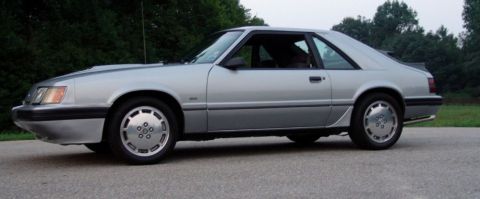
1990 Ford Mustang/
Photo
supermotors.net/registry/media/844133
Ford Mustang Front Crossmember Blueprint - A-Arm & R&P Mount Dimensions
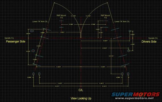
Dimensioned CAD blueprint of front suspension geometry showing spindle, lower A-arm, and rack-and-pinion mount centerlines, view looking up.
This is a CAD-style dimensional blueprint titled "View Looking Up," drawn by D. Rahn and dated 1/2/2011. It depicts the underside layout of a front suspension crossmember/K-member area, showing the passenger side (left) and drivers side (right) relative to a vertical centerline (C/L) and a horizontal Spindle C/L. Marked features include the Lower "A" Arm centerlines on both sides, rack-and-pinion (R&P) mount centerlines, and several mounting hole locations (drawn as small ovals/circles). Numerous precise dimensions are given, such as R&P mount offsets of 6.7500" and 8.7500" from the centerline, angular measurements of 74.1150° on each side, lower A-arm pivot dimensions (9.3438", 6.6250", 3.2500", 3.0395", 3.0000", 11.8823"), driver-side dimensions (2.4062", 4.4568", 16.9688", 16.6625", 12.5133"), symmetric mounting hole spans of 15.4063", 14.4075", and 16.4375" each side of center, and 2.0300" hole pair spacing at the lower mounts. A reader could use this drawing to locate or fabricate suspension mounting points, verify crossmember geometry, or position a rack-and-pinion steering unit. The drawing itself does not state a vehicle make, model, or year of applicability.
Is this accurate? Sign in to help verify it.
Frequently asked questions
- What view does this blueprint show?
- It is labeled "View Looking Up," showing the underside layout with Passenger Side on the left and Drivers Side on the right, referenced to a centerline (C/L) and Spindle C/L.
- How far are the rack-and-pinion (R&P) mounts from the centerline?
- The left R&P mount centerline is 6.7500" from center and the right is 8.7500" from center, with vertical offsets of 5.9687" and 3.7187" shown.
- What angle are the lower A-arm centerlines drawn at?
- Both sides show an angle of 74.1150° relative to the layout.
- What is the spacing of the lower mounting hole pairs?
- Each lower mounting hole pair is spaced 2.0300" apart, located 14.4075" and 16.4375" from the centerline on each side.
- Who made this drawing and when?
- The drawing is signed D. Rahn and dated 1/2/2011.
Comments
More from this build


No comments yet.