Home/
Registry/
Ford/
Mustang/
1979-1993/
1990 Ford Mustang/
Photo
supermotors.net/registry/media/427454
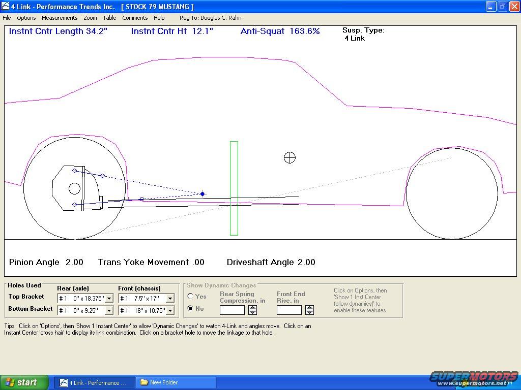
Stock 1979 Ford Mustang 4-Link Rear Suspension Geometry - Anti-Squat & IC Data
Reference · 1979-1993 MustangAll 8 schematics
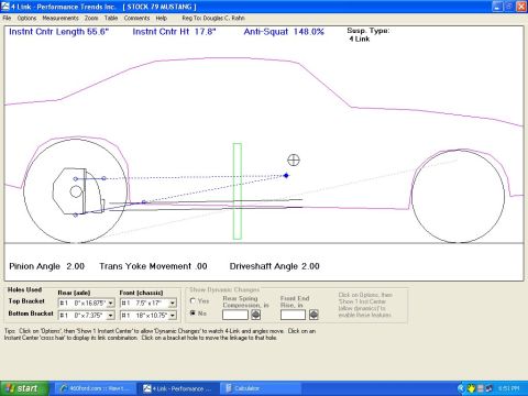
4-Link suspension geometry schematic showing instant-center and anti-squat figures with bracket-hole settings for a Mustang rear suspension.
Part of 1979-1993 Ford Mustang Schematics
This is a screenshot of Performance Trends Inc.'s '4 Link' suspension analysis software, showing a saved project titled 'STOCK 79 MUSTANG' (registered to Douglas C. Rahn). The screen displays a side-view schematic of a Fox-body Mustang with the 4-link rear suspension geometry plotted, including link lines converging toward an instant center. Calculated values shown across the top are: Instant Center Length 34.2", Instant Center Height 12.1", and Anti-Squat 163.6%, with suspension type identified as '4 Link'. Below the diagram the program reports Pinion Angle 2.00, Trans Yoke Movement .00, and Driveshaft Angle 2.00. A 'Holes Used' table lists bracket hole coordinates: Top Bracket rear (axle) #1 at 0" x 18.375" and front (chassis) #1 at 7.5" x 17"; Bottom Bracket rear #1 at 0" x 9.25" and front #1 at 18" x 10.75". A 'Show Dynamic Changes' panel (set to No) offers fields for Rear Spring Compression and Front End Rise. A reader can learn the stock 1979 Mustang 4-link geometry values and anti-squat characteristics as computed by this software, useful as a baseline for Fox-body rear suspension tuning.
Is this accurate? Sign in to help verify it.
Frequently asked questions
- What is the anti-squat percentage for a stock 1979 Mustang 4-link rear suspension?
- The Performance Trends 4 Link software calculates the stock 79 Mustang's anti-squat as 163.6%.
- Where is the instant center on a stock 79 Mustang 4-link setup?
- The instant center is located at a length of 34.2 inches and a height of 12.1 inches, per the software's calculation.
- What pinion and driveshaft angles are shown for the stock configuration?
- Pinion angle is 2.00, driveshaft angle is 2.00, and trans yoke movement is .00.
- What bracket hole locations does the model use?
- Top bracket: rear (axle) #1 at 0" x 18.375", front (chassis) #1 at 7.5" x 17". Bottom bracket: rear #1 at 0" x 9.25", front #1 at 18" x 10.75".
- What software produced this diagram?
- It is a screenshot of '4 Link' by Performance Trends Inc., which analyzes 4-link suspension geometry and can show dynamic changes such as rear spring compression and front end rise.

No comments yet.