Home/
Registry/
Ford/
Taurus/
1992-1995/
1993 Ford Taurus/
Photo
supermotors.net/registry/media/180959
Ford Taurus Multi-Function Switch Test Procedure - Wiper/Washer Pinout & Ohms

Reference · 1992-1995 TaurusAll 37 wiring diagrams
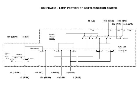
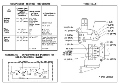
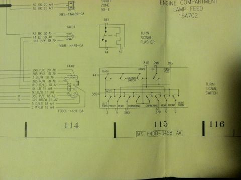
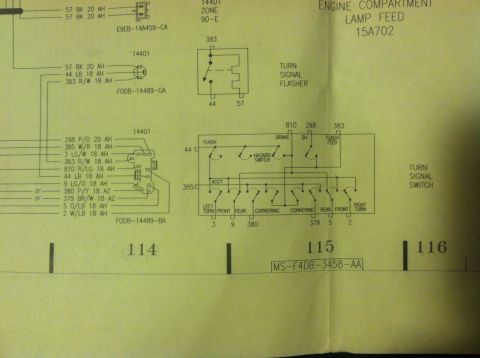
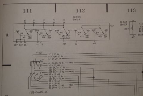
Multi-function switch service diagram: wiper/washer schematic, labeled terminal/wire-color map, and component-testing chart (e.g. wiper OFF 47.6k, INT 11.33k, LO 4.08k ohm).
Part of 1992-1995 Ford Taurus Wiring Diagrams
This document is a component testing reference for the wiper/washer portion of a Ford multi-function switch (turn signal/wiper stalk switch). The left side contains a component testing procedure table that tells a technician which terminals to connect a self-powered test light or ohmmeter to, which switch positions to select, and the resistance readings a good switch should produce. For the washer switch circuit (terminals 590 DB/W and 993 BR/W), pressing the washer button should show a closed circuit and releasing it 103.3k ohm. For the wiper switch circuit (terminals 589 O and 993 BR/W), expected readings are 47.6k ohm (OFF), 11.33k ohm (INT), 4.08k ohm (LO), and a closed circuit (HI). The interval time adjust test should show smoothly increasing resistance from 3.3k ohm to 103.3k ohm as the control is rotated toward OFF. Below the table is an internal schematic of the wiper/washer switching with resistor values (100k, 3.3k, 36.27k, 4.08k, 7.25k ohm). The right side shows a terminal/connector pinout diagram of the multi-function switch identifying circuit numbers and wire colors, including 810 (R/LG), 383 (R/W), 3 (LG/W), 385 (W/R), 298 (P/O), 2 (W/LB), 15 (R/Y), 13 (R/BK), 12 (LG/BK), 196 (DB/O), 44 (LB), 9 (LG/O), 380 (P/Y), 5 (O/LB), 379 (BR/W), 589 (O), 993 (BR/W), and 590 (DB/W).
Is this accurate? Sign in to help verify it.
Frequently asked questions
- How do I test the wiper switch circuit on the multi-function switch?
- Connect an ohmmeter to terminals 589 (O) and 993 (BR/W). A good switch reads 47.6k ohm in OFF, 11.33k ohm in INT, 4.08k ohm in LO, and a closed circuit in HI.
- What terminals are used to test the washer switch circuit?
- Terminals 590 (DB/W) and 993 (BR/W). With the wiper switch OFF, pushing the washer switch should show a closed circuit; releasing it should show 103.3k ohm.
- What should the interval time adjust test show?
- With the ohmmeter on terminals 590 (DB/W) and 993 (BR/W) in INT and OFF, rotating the control toward OFF should show smoothly increasing resistance from 3.3k ohm minimum to 103.3k ohm maximum. In LO and HI it should read 3.3k ohm.
- What wire colors correspond to the wiper circuits 589, 590 and 993?
- Circuit 589 is Orange (O), circuit 590 is Dark Blue/White (DB/W), and circuit 993 is Brown/White (BR/W).
- What other circuits appear on the multi-function switch connector?
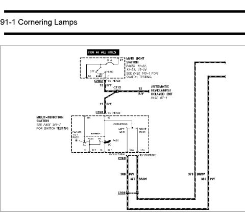
- The terminal diagram shows 810 (R/LG), 383 (R/W), 3 (LG/W), 385 (W/R), 298 (P/O), 2 (W/LB), 15 (R/Y), 13 (R/BK), 12 (LG/BK) (with a base-vehicle variant), 196 (DB/O), 44 (LB), 9 (LG/O), 380 (P/Y), 5 (O/LB), 379 (BR/W), 589 (O), 993 (BR/W), and 590 (DB/W).






No comments yet.