Home/
Registry/
Ford/
Taurus/
1992-1995/
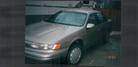
1993 Ford Taurus/
Photo
supermotors.net/registry/media/180958
Ford Taurus Multi-Function Switch Test Procedure - Turn/Hazard/Dimmer Continuity

Reference · 1992-1995 TaurusAll 12 service procedures
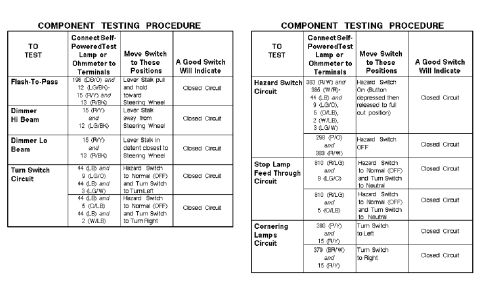

Component testing procedure tables listing terminals, switch positions and expected good-switch results for lighting circuits.
Part of 1992-1995 Ford Taurus Service Procedures
This document contains two side-by-side "Component Testing Procedure" tables for a multi-function switch (turn signal/dimmer/hazard lever stalk switch). Each row tells the tester which circuit terminals to connect a self-powered test lamp or ohmmeter to (identified by circuit numbers and wire color codes, e.g., 196 DB/O, 15 R/Y, 44 LB, 383 R/W, 810 R/LG), what position to move the switch or lever stalk into, and that a good switch will indicate a closed circuit. Covered tests include Flash-To-Pass, Dimmer Hi Beam, Dimmer Lo Beam, Turn Switch Circuit (left and right), Hazard Switch Circuit (on and off), Stop Lamp Feed Through Circuit (both sides), and Cornering Lamps Circuit (left and right). Wire colors referenced include dark blue/orange, light green/black, red/yellow, red/black, light blue, light green/orange, light green/white, orange/light blue, white/light blue, red/white, white/red, purple/orange, red/light green, purple/yellow, and brown/white. A reader can use this to bench-test or in-vehicle continuity-test the multi-function switch to confirm proper operation of each internal switch contact before replacing it. The document itself carries no year, make, or model identification.
Is this accurate? Sign in to help verify it.
Frequently asked questions
- How do I test the Flash-To-Pass function of the multi-function switch?
- Connect a self-powered test lamp or ohmmeter to terminals 196 (DB/O) and 12 (LG/BK), then 15 (R/Y) and 13 (R/BK), pull and hold the lever stalk toward the steering wheel; a good switch will indicate a closed circuit.
- Which terminals are used to test the dimmer high beam circuit?
- Terminals 15 (R/Y) and 12 (LG/BK), with the lever stalk moved away from the steering wheel. A good switch shows a closed circuit.
- How is the hazard switch circuit tested?
- With the hazard switch on (button depressed then released to full out position), check for closed circuit between 383 (R/W) and 385 (W/R)-44 (LB) and 9 (LG/O), 5 (O/LB), 2 (W/LB), 3 (LG/W). With the hazard switch off, check 298 (P/O) and 383 (R/W) for a closed circuit.
- What terminals test the cornering lamps circuit?
- Turn switch to left: 380 (P/Y) and 15 (R/Y); turn switch to right: 379 (BR/W) and 15 (R/Y). A good switch indicates a closed circuit.
- How do I test the stop lamp feed through circuit?
- With the hazard switch at Normal (OFF) and the turn switch in Neutral, check for closed circuit between 810 (R/LG) and 9 (LG/O), and between 810 (R/LG) and 5 (O/LB).

No comments yet.