Home/
Registry/
Ford/
Fairlane/
1966-1967/
1966 Ford Fairlane/
Photo
supermotors.net/registry/media/244047
Ford FE V8 Firing Order & Distributor Cap Diagram - 1966 Fairlane 390
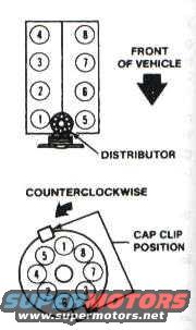
Reference · 1966-1967 FairlaneAll 3 schematics
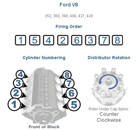
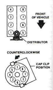
Distributor diagram showing cylinder numbering, firing order and counterclockwise cap clip position.
Part of 1966-1967 Ford Fairlane Schematics
This document is a small schematic diagram showing the cylinder numbering, distributor location, and distributor cap terminal arrangement for a V8 engine, uploaded as a firing order reference for an FE-series Ford engine. The top illustration shows the engine viewed from above with the front of the vehicle indicated by an arrow: the left cylinder bank is numbered 4-3-2-1 (front to rear reading bottom to top as drawn) and the right bank 8-7-6-5, with the distributor located at the front of the engine. The lower illustration shows the distributor cap viewed from above, with an arrow indicating counterclockwise rotor rotation and a callout marking the cap clip position for correct orientation. Numbered terminals around the cap show where each spark plug wire connects. A reader can use this diagram to identify each cylinder's number, determine the direction the rotor turns, and route spark plug wires from the distributor cap to the correct cylinders. The diagram itself does not state a year, model, or engine displacement, but the filename and album context indicate it is intended for FE-series Ford big-block engines such as the 390 in a 1966 Ford Fairlane.
Is this accurate? Sign in to help verify it.
Frequently asked questions
- Which direction does the distributor rotor turn on this engine?
- The diagram indicates the distributor rotates counterclockwise.
- How are the cylinders numbered on this V8?
- Viewed from above with the front of the vehicle at the top, one bank is numbered 1-2-3-4 (front to rear) and the other bank 5-6-7-8 (front to rear).
- Where is the distributor located on this engine?
- The distributor is at the front of the engine, as shown by the callout in the top diagram.
- How do I orient the distributor cap correctly?
- The lower diagram marks the cap clip position, which is used as a reference for orienting the cap and identifying the numbered terminal positions.


No comments yet.