Home/
Registry/
Ford/
Fairlane/
1966-1967/
1966 Ford Fairlane/
Photo
supermotors.net/registry/media/450698
Cam Lobe Lift Measurement Diagram - Calculate Valve Lift by Rocker Ratio
Reference · 1966-1967 FairlaneAll 3 schematics
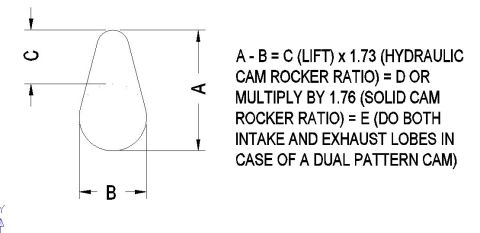
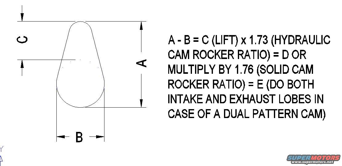
Camshaft lobe diagram showing lift measurement points with a rocker-ratio formula for hydraulic and solid cams.
Part of 1966-1967 Ford Fairlane Schematics
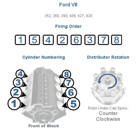
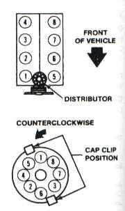
This document is a simple technical sketch/schematic showing how to measure a camshaft lobe to determine valve lift. The drawing depicts a single cam lobe (egg-shaped profile) with three dimension callouts: A is the overall lobe height from nose to base circle, B is the base circle diameter (lobe width), and C represents the resulting lobe lift. The accompanying instructions state that subtracting B from A gives C, the lobe lift. That lobe lift value is then multiplied by the rocker arm ratio to obtain gross valve lift: multiply by 1.73 for a hydraulic cam rocker ratio (result D), or by 1.76 for a solid cam rocker ratio (result E). The note also instructs the user to perform this measurement on both intake and exhaust lobes if the camshaft is a dual-pattern grind (different intake and exhaust profiles). This is a general cam-measurement reference; it was uploaded to a 1966 Ford Fairlane gallery alongside FE engine firing order and clutch Z-bar diagrams, but the sketch itself lists no specific year, make, model, or part numbers. A reader can learn the basic method for calculating valve lift from a camshaft removed from (or measured in) an engine using simple external measurements.
Is this accurate? Sign in to help verify it.
Frequently asked questions
- How do I calculate cam lobe lift from lobe measurements?
- Measure the overall lobe height (A) and the base circle diameter (B). Subtract: A - B = C, which is the lobe lift.
- How do I convert lobe lift to valve lift?
- Multiply lobe lift (C) by the rocker ratio: x 1.73 for a hydraulic cam rocker ratio (= D), or x 1.76 for a solid cam rocker ratio (= E).
- What do the letters A, B, and C mean on the diagram?
- A is the total height of the cam lobe, B is the width of the base circle, and C is the lobe lift (the difference between A and B).
- Do I need to measure both intake and exhaust lobes?
- Yes, if the camshaft is a dual pattern cam, the document says to do both intake and exhaust lobes.
No comments yet.