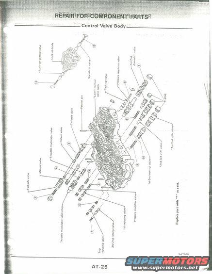
This diagram illustrates the internal components of a control valve body, detailing various valves and their connections.
9v 33%;: in? E e 2.3 slam Jaw >33 use, ,5 :52: .22 .3 23m 3 a as? 5.6:; Cdntrol Valve Body ' can) E55 o 5:332:25 2.: 3:55 2:33 e. 2: 3:25 a s a T A s do. u an :2. 5.! :1: 8.3-: 3?, 5 3?: . m2? :5 Enucn. 5.5 358 Ed: m>_ u.um:-u E 9:55 .9, 9.6.52 2 .2: use: 9.2.5 23 9.6.63 8 3:: 2.5 55.35:. 2:55 25 AT
Comments
More from this build


No comments yet.