SuperMotors SuperMotors SUPERMOTORS Search: try “orange Bronco on 35s”
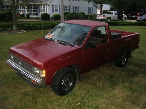
Home/ Registry/ Nissan/ Micra/ 1983-1992/ 1990 Nissan Micra/ Photo supermotors.net/registry/media/252953

Service manual page on automatic transmission control valve body…

Service manual page on automatic transmission control valve body with spring chart and disassembly diagrams
Service manual page on automatic transmission control valve body with spring chart and disassembly diagramsOriginal file
Service manual page on automatic transmission control valve body with spring chart and disassembly diagrams

87 Service ManualView all 403

Disassembly page with exploded breakdown of internal gears, carriers, clutches, snap rings and thrust bearings Service manual page AT-20 showing automatic transmission disassembly steps with diagrams Service manual page AT-21 showing automatic transmission disassembly steps 28 through 31 Service manual page on oil pump repair with diagrams and part tables Oil pump exploded diagram with gears, housing, plate, seal rings, thrust washer plus clearance inspection figu Service manual page AT-24 with oil pump assembly diagrams Exploded diagram of automatic transaxle control valve body identifying each valve, spring, plug and separator Service manual page on automatic transmission control valve body with spring chart and disassembly diagrams Control valve body cleaning and assembly notes with valve body photos and separator plate inspection figures Service manual page AT-28 on automatic transaxle control valve body assembly and adjustment High-reverse clutch exploded diagram with piston, springs, plates, snap rings plus disassembly figures Service manual page AT-30 showing illustrated high-reverse clutch drum reassembly steps Service manual page AT-31 on high-reverse clutch clearance with retainer plate part table Forward clutch exploded diagram with piston, springs, drive and driven plates, snap rings plus service notes Low and reverse brake exploded diagram showing piston, retainer, drive and driven plates and snap ring stacked Brake band and band servo exploded diagram with servo piston, springs, O-rings, washer plus band inspection fi 403photos in this albumView all

Scanned automatic-transmission service-manual page AT-26, 'Repair for Component Parts: Control Valve Body,' showing a valve-body spring free-length chart and illustrated disassembly and inspection steps.

AI caption · Photo 208 of 412

VALVE BODY SPRING CHART fFree length As Installed length llllllll Ianre dxa. sAToss Numbers of each valve spring listed in table below are the same as those in the figure on the previous page. Control Valve Body (Condl _ Valve spring Free length mm (in) (D Pressure regulate! valve 46.4 (1.827) Throttle valve 33.4 (1315) Fail-safe valve 231 (0.909) 3 Throttle modulator valve 22.5 (0.856) 6) Pressure modier valve 251 (0.988) @ lst reducing valve 21.4 (0.843) 6; 3rd~2nd timlng valve 23.4 (0.921) Back up valve 18.8 (0.740) @ 1st-2nd shift valve 38.9 (1531) 2nd-3rd shift valve 45.7 (1.799) 3rd-2nd downshift valve 389 (1.531) Top reducmg valve 20.6 (0.811) Speed cut valve 20.6 (0.3) {D Lockup control valve 20.6 (0.811) Elli": hlt till now pressure modifier valve spring is the same type as the one which was removed. DISASSEMBLY 1. Remove oil strainer and magnet. 2. Disassemble valve body and its Teainl'lg attaching bolts and nuts to carefully separate lower body, separator plate and upper body. SATIN? 3. During valve body separation, do not lose the 6 steel balls on valve upper body. Parallel pin Manual valve was removed when valve body was removed from transaxle. Include valve in subse quent inspection and service sequence. INSPECTION A newly manufactured valve body represents precision manufactured valves assembled with close tolerances into precision bores of the valve bodv- AT-26

Is this accurate? Sign in to help verify it.
Comments

No comments yet.

More 1983-1992 Micras