Home/
Registry/
Ford/
Probe/
1989-1992/
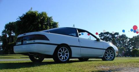
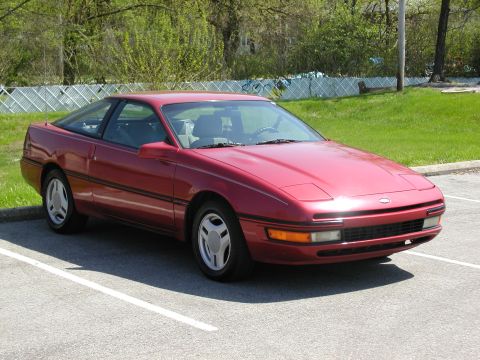
1992 Ford Probe/
Photo
supermotors.net/registry/media/259655
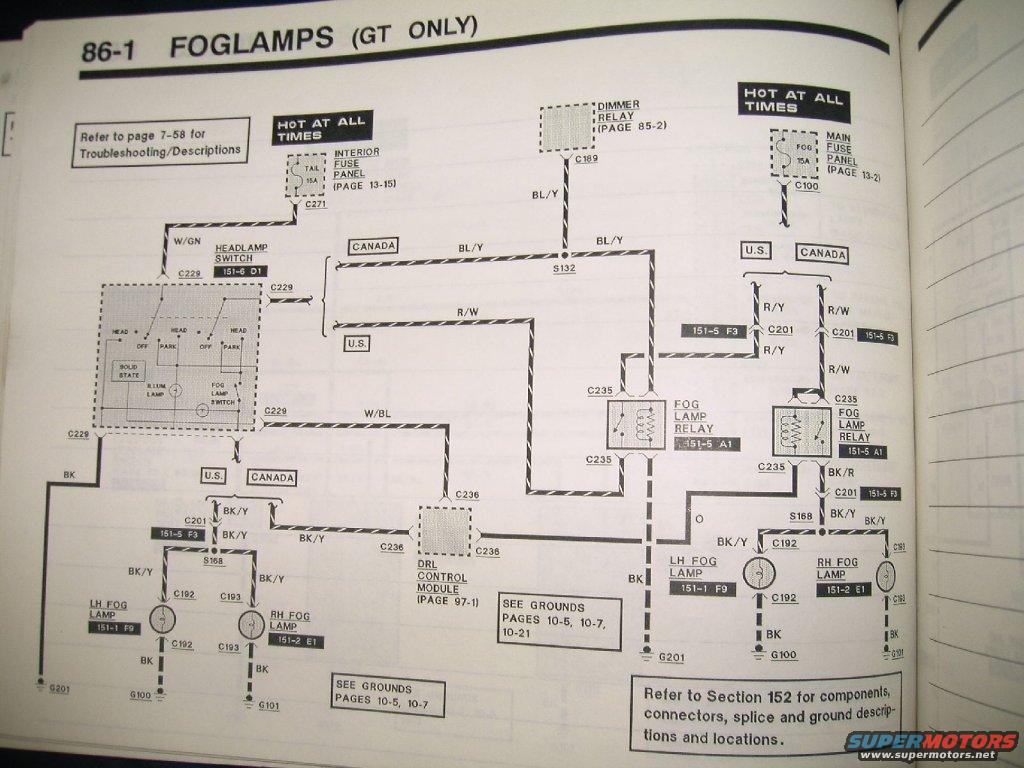
Ford Probe GT Foglamp Wiring Diagram (Page 86-1) - US & Canada Circuits
Reference · 1989-1992 ProbeAll 2 wiring diagrams
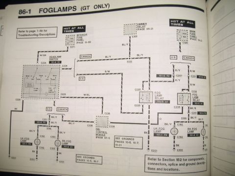
Scanned service-manual wiring diagram for GT-only foglamps showing fog lamp relays, switch, connectors and color-coded circuits.
Part of 1989-1992 Ford Probe Wiring Diagrams
This document is page 86-1 of a Ford factory wiring diagram manual (EVTM) covering the foglamp circuit for GT models only, uploaded as applying to a 1992 Ford Probe GT. The diagram shows two power sources that are hot at all times: the TAIL 15A fuse in the interior fuse panel (connector C271, page 13-15) and the FOG 15A fuse in the main fuse panel (connector C100, page 13-2). Power flows through the headlamp switch (grid 151-6 D1, connector C229), which contains a solid-state section, illumination lamp, and integral fog lamp switch. The circuit differs between U.S. and Canadian versions: Canadian vehicles route through the dimmer relay (page 85-2, C189) and a DRL control module (page 97-1, C236), while U.S. vehicles use a more direct path. Two fog lamp relays (151-5 A1, connector C235) control the LH fog lamp (151-1 F9, C192) and RH fog lamp (151-2 E1, C193). Wire colors include W/GN, BL/Y, R/W, R/Y, W/BL, BK/Y, BK/R, O (orange), and BK grounds to G100, G101, and G201. Cross-references point to troubleshooting on page 7-58, ground pages 10-5, 10-7, 10-21, and Section 152 for connector and ground locations.
Is this accurate? Sign in to help verify it.
Frequently asked questions
- What fuses power the fog lamps on the Probe GT?
- Two hot-at-all-times fuses: the TAIL 15A fuse in the interior fuse panel (page 13-15, connector C271) and the FOG 15A fuse in the main fuse panel (page 13-2, connector C100).
- Are the fog lamps available on all Probe models?
- No: the diagram is titled 'FOGLAMPS (GT ONLY)', so this circuit applies only to GT models.
- What is the difference between the U.S. and Canadian fog lamp circuits?
- The diagram shows separate U.S. and CANADA paths. The Canadian circuit routes through the dimmer relay (page 85-2, C189) and the DRL control module (page 97-1, C236), while the U.S. circuit uses a more direct path with R/Y and BK/R wiring.
- Which connectors serve the left and right fog lamps?
- The LH fog lamp (grid 151-1 F9) uses connector C192 and the RH fog lamp (grid 151-2 E1) uses connector C193, with BK ground wires to grounds G201, G100, and G101.
- Where can I find troubleshooting information for this fog lamp circuit?
- The diagram says to refer to page 7-58 for Troubleshooting/Descriptions, grounds on pages 10-5, 10-7, and 10-21, and Section 152 for components, connectors, splice and ground descriptions and locations.
No comments yet.