Home/
Registry/
Ford/
Probe/
1989-1992/
1992 Ford Probe/
Photo
supermotors.net/registry/media/264158
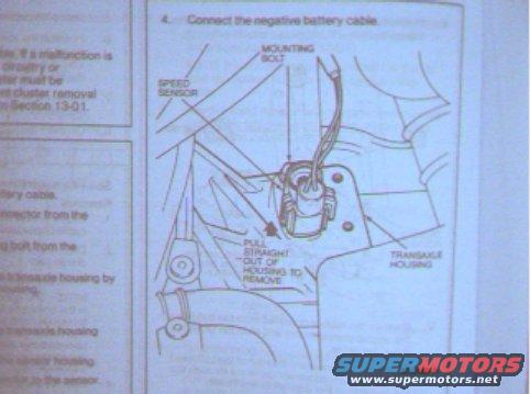
1992 Ford Probe Speed Sensor Removal Diagram - Transaxle Housing Location
Reference · 1989-1992 ProbeAll 4 service procedures
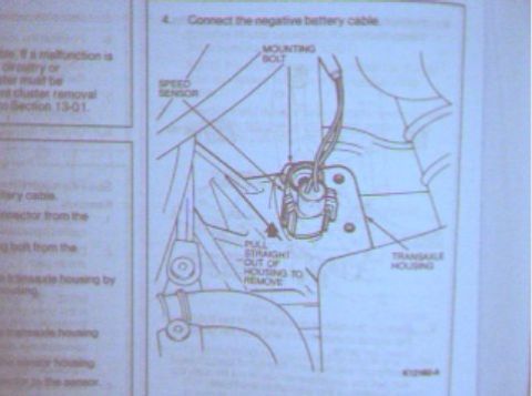
Service procedure figure showing how to pull the speed sensor straight out of the transaxle housing, with mounting bolt callout.
Part of 1989-1992 Ford Probe Service Procedures
This is a scanned page from a Ford service manual showing the removal and installation procedure for a vehicle speed sensor mounted in the transaxle housing. The visible portion includes step 4 of the installation procedure ('Connect the negative battery cable') and a labeled line-art illustration of the speed sensor location. The diagram identifies the SPEED SENSOR, its MOUNTING BOLT, and the TRANSAXLE HOUSING, with an instruction callout stating to 'PULL STRAIGHT OUT OF HOUSING TO REMOVE' the sensor. A figure reference number (K12160-A) appears at the bottom of the illustration. A partially visible left column contains fragments of the removal steps, referencing disconnecting the battery cable, disconnecting a connector, removing a bolt from the transaxle housing, and a note directing the reader to Section 13-01 for instrument cluster removal if a malfunction is suspected in related circuitry. The scan was uploaded as documentation for a 1992 Ford Probe, and the transaxle-mounted sensor arrangement is consistent with that application, though the page itself does not state a year or model. Readers can learn where the speed sensor is located, how it is retained (single mounting bolt), and that it pulls straight out of the transaxle housing for removal.
Is this accurate? Sign in to help verify it.
Frequently asked questions
- Where is the speed sensor located according to this diagram?
- The diagram shows the speed sensor mounted in the transaxle housing, retained by a mounting bolt.
- How is the speed sensor removed from the transaxle?
- Per the diagram callout, after removing the mounting bolt the sensor is pulled straight out of the housing to remove it.
- What is the final step of the installation procedure shown?
- Step 4 states: 'Connect the negative battery cable.'
- What section does the manual reference for instrument cluster removal?
- The partially visible left-column text references Section 13-01 for cluster removal.

No comments yet.