Home/
Registry/
Ford/
Fairlane/
1966-1967/
1966 Ford Fairlane/
Photo
supermotors.net/registry/media/293062
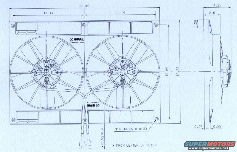
SPAL Dual Electric Fan Blueprint - Dimensions & Mounting Hole Layout
Reference · 1966-1967 FairlaneAll 3 blueprints

Dimensioned engineering drawing of a SPAL dual cooling fan and shroud assembly with mounting hole spacing.
Part of 1966-1967 Ford Fairlane Blueprints
This document is a dimensional blueprint/technical drawing of a SPAL dual electric cooling fan assembly (SPAL, Correggio, Italy). It shows a front view of two fans mounted in a common rectangular shroud and a side (profile) view of one fan. Key dimensions given (apparently in inches) include an overall shroud width of 23.46 and overall height of 16.26, with the two fan centers each located 11.14 from the shroud edges. Mounting hole vertical spacing is 14.80, and the shroud has six mounting holes of 0.33 diameter (noted as "N° 6 HOLES Ø 0.33"). The side view shows an overall depth of 4.25, with intermediate dimensions of 2.6, 1.29, 0.37, and 0.55 defining shroud and motor projection depths. A dimension of 16.93±0.4 is called out with an asterisk noted as measured "FROM CENTER OF MOTOR," apparently locating the wiring leads/connectors. The drawing shows two-wire leads exiting the bottom of the assembly with connectors. A reader can use this drawing to verify fitment clearances, mounting hole layout, and overall packaging of the SPAL dual fan assembly, for example when planning an electric fan conversion on a vehicle radiator.
Is this accurate? Sign in to help verify it.
Frequently asked questions
- What are the overall dimensions of this SPAL dual fan assembly?
- The drawing shows an overall width of 23.46, an overall height of 16.26, and an overall depth of 4.25.
- How many mounting holes does the shroud have and what size are they?
- The drawing calls out "N° 6 HOLES Ø 0.33", six mounting holes of 0.33 diameter.
- What is the spacing of the fan centers?
- Each fan center is located 11.14 from the side of the shroud, on the 23.46-wide assembly.
- What is the vertical mounting hole spacing?
- The mounting holes are spaced 14.80 apart vertically, within the 16.26 overall height.
- How deep does the assembly project?
- The side view shows a total depth of 4.25, with intermediate depths of 2.6, 1.29, 0.37, and 0.55; a 16.93±0.4 dimension is measured from the center of the motor.

No comments yet.