Home/
Registry/
Ford/
Fairlane/
1966-1967/
1966 Ford Fairlane/
Photo
supermotors.net/registry/media/866207
Ford Fairlane Clutch Z-Bar Linkage Blueprint Sketch - Equalizer Bar CAD Views

Reference · 1966-1967 FairlaneAll 3 blueprints
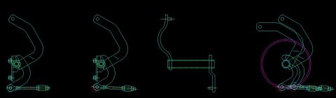
Multi-view CAD engineering drawing of a suspension bracket and linkage assembly.
Part of 1966-1967 Ford Fairlane Blueprints
This document is a computer-drawn (CAD) blueprint sketch showing multiple views of a clutch equalizer bar assembly, commonly known as a Z-bar, along with its adjustable clutch release rod and mounting bracket. Four views are arranged left to right: two nearly identical side-profile views showing the bent Z-bar lever with pivot bracket, bushing, and the threaded adjustable clutch rod with clevis ends; a third view depicting the cross-shaft tube of the Z-bar with its two bent lever arms from a different orientation; and a fourth composite view that overlays large magenta and cyan circles, apparently representing a bellhousing or flywheel clearance circle, onto the Z-bar and clutch rod geometry to illustrate fitment or clearance. The drawing contains no visible dimensions, text labels, part numbers, or notes, so it serves purely as a visual/geometric reference for the shape and arrangement of the clutch linkage components. Given the uploader's album context (files named 66-390-zbar, 67-390-zbar, etc.), a reader can use this sketch to understand the general form of the mechanical clutch linkage Z-bar used on a mid-1960s Ford Fairlane, but no applicability data is stated within the document itself.
Is this accurate? Sign in to help verify it.
Frequently asked questions
- What does this blueprint show?
- It shows four CAD-drawn views of a clutch equalizer (Z-bar) linkage assembly, including the bent Z-bar lever, its pivot bracket and bushing, and an adjustable threaded clutch rod with clevis ends.
- Does the drawing include dimensions or part numbers?
- No. The sketch contains no legible dimensions, part numbers, or text annotations, only line geometry of the components.
- What are the circles in the rightmost view?
- The rightmost view overlays large magenta and cyan circles on the Z-bar and clutch rod, apparently to illustrate clearance or fitment of the linkage around a circular component such as a bellhousing.
- How many views of the Z-bar are shown?
- Four views: two side-profile views of the Z-bar with clutch rod, one view of the cross-shaft tube with its bent lever arms, and one composite view with circular clearance overlays.
No comments yet.