Home/
Registry/
Ford/
Bronco/
1966-1977/
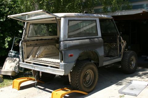
1974 Ford Bronco/
Photo
supermotors.net/registry/media/307402
Ford Bronco Transfer Case Removal & Installation - Shop Manual Page 6-20
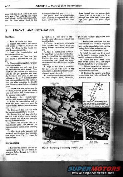
Manual-shift transmission/transfer case service page: describes power flow to front and rear axles and step-by-step transfer case removal and installation procedure with a fabricated input-shaft holding tool.
This is page 6-20 from a Ford factory shop manual, Group 6, Manual Shift Transmission, covering the removal and installation of the transfer case. The page begins by finishing a power-flow description: direct drive to the rear axle flows through the rear output shaft, while drive to the front axle flows through the idler shaft drive gear, high-speed gear, and front output shaft. The Removal section gives a 13-step procedure: raising the vehicle, removing the transfer case shield, draining lubricant, disconnecting the drive shafts, speedometer cable and shift rods, inserting a fabricated holding tool to keep the input shaft roller bearings from dropping into the transmission case, removing the crossmember and shift lever bracket, and lowering the transfer case with a transmission jack. The Installation section provides 12 steps that reverse the process, including torquing bolts to specifications, securing crossmember bolts with lock wire, reconnecting the speedometer cable and drive shafts, and refilling the transmission and transfer case with recommended lubricant. Figure 2 is a photograph showing removal/installation of the transfer case with callouts for the fabricated tool, front axle drive shaft, transmission jack, and rear axle drive shaft. An inset diagram shows how to fabricate the holding tool from 3/8-inch drill rod with a 5-13/16" length, an L-bend, and a welded 2" extension.
Is this accurate? Sign in to help verify it.
Frequently asked questions
- What is the purpose of the fabricated tool used when removing the transfer case?
- With the first-reverse gear shift lever placed in the first gear position, the fabricated tool is inserted to prevent the input shaft roller bearings from dropping into the transmission case when separating the transfer case from the transmission and output shaft.
- How do you make the transfer case holding tool?
- Per the diagram, the holding tool can be fabricated from 3/8-inch diameter drill rod by bending one end to an L-shape and welding a 2-inch extension to the other. The rod length shown is 5-13/16 inches with 2-inch ends.
- What must be disconnected before removing the transfer case?
- The front and rear drive shafts at the transfer case, the speedometer cable at the transfer case, the shift rods from the transmission shift levers, and the shift rod from the transfer case shift lever bracket.
- How are the crossmember-to-transfer case adapter bolts secured during installation?
- The crossmember-to-transfer case adapter bolts, insulators, plates, and washers are installed and the bolts are secured with lock wire.
- How does power flow to the front axle in this transfer case?
- Direct drive to the front axle flows through the idler shaft drive gear, high-speed gear, and front output shaft, while direct drive to the rear axle flows through the rear output shaft.
Comments
More from this build

No comments yet.